background image

DA-682A-DPP Hardware 

Hardware Installation 


2-3 

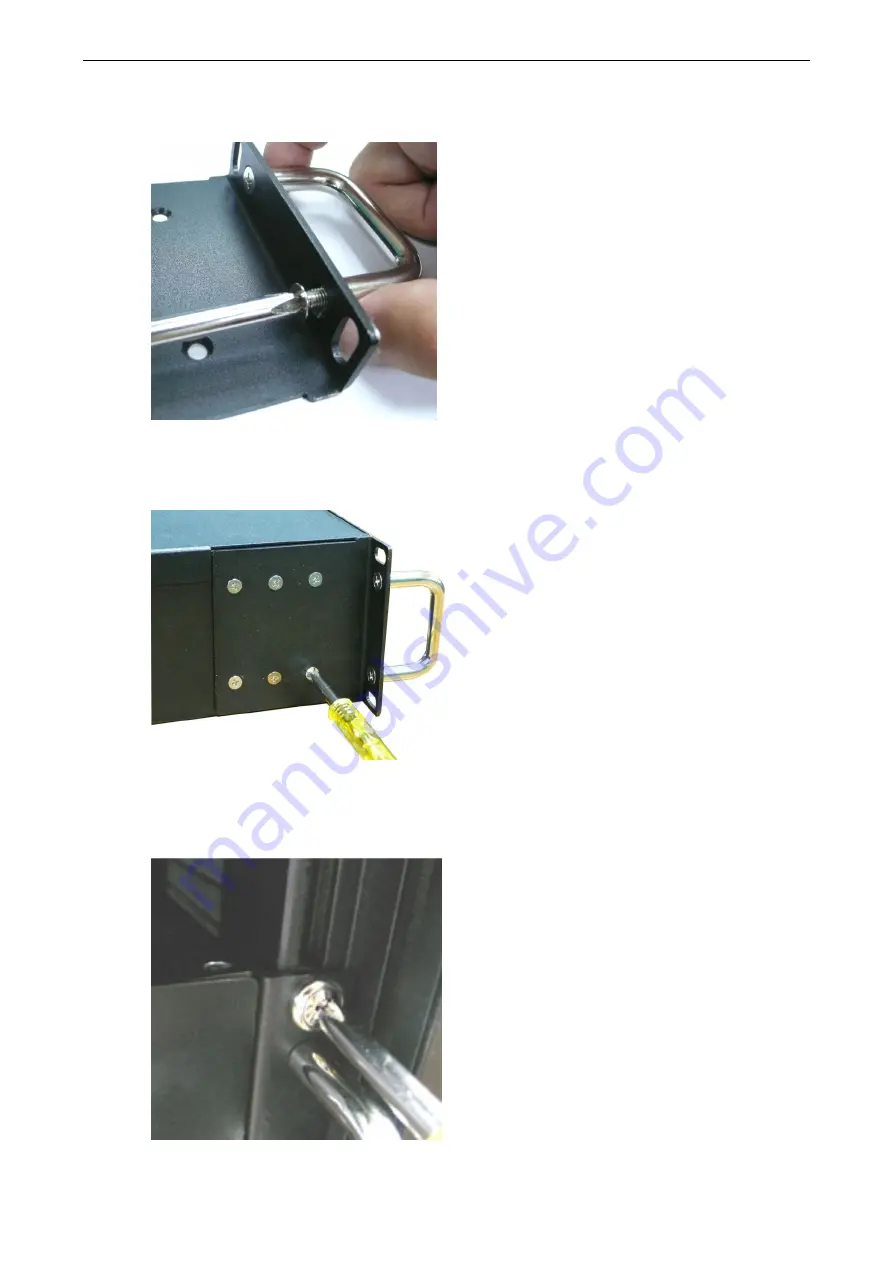
Step 2:  Install the handles 

Use 4 FMSM5X10 screws (2 on each bracket) to attach the handles to the brackets. 


Step 3:    Install the brackets 

Use 6 FMSM4X6 screws to attach a bracket to one side of the DA-682A-DPP. Repeat this procedure on the other 
side. 


Step 4:    Installing the DA-682A-DPP on a rack. 

Gently slide the DA-682A-DPP onto the rack, and then use screws (provided by the rack supplier) to fix the 
bracket to the rail. 


Summary of Contents for DA-682A-DPP Series

Page 1: ...DA 682A DPP Hardware User s Manual Edition 1 0 March 2016 www moxa com product 2016 Moxa Inc All rights reserved ...

Page 2: ...es to this manual or to the products and or the programs described in this manual at any time Information provided in this manual is intended to be accurate and reliable However Moxa assumes no responsibility for its use or for any infringements on the rights of third parties that may result from its use This product might include unintentional technical or typographical errors Changes are periodi...

Page 3: ...ATA Hard Disks 12 Installing and Removing Expansion Modules 15 DA SP08 I DB DA SP08 DB DA SP08 I EMC4 DB Serial Expansion Modules 16 DA SP08 I TB DA SP08 I EMC4 TB Serial Expansion Modules 16 DA IRIGB 4DIO PCI104 EMC4 Module 17 DA IRIGB 4DIO PCI104 EMC4 Pin Assignments 17 Connecting a DA IRIGB B S Module 18 3 BIOS Setup 1 Entering the BIOS Setup 2 Main Information 3 Advanced Settings 3 Boot Config...

Page 4: ...Discard Changes 11 Upgrading the BIOS 12 A Safety Installation Instructions 1 ...

Page 5: ... management please refer to the user s manual for the operating system installed on the computer The following topics are covered in this chapter Overview Model Descriptions and Package Checklist Appearance Dimensions Features Hardware Block Diagram DA 682A DPP Basic System Hardware Specifications Basic Systems Expansion Modules Software Selectable Serial Ports Time Synchronization and DI DO Ports...

Page 6: ...software recovery system that allows engineers to 1 automatically recover an OS system after a crash and 2 set up manual recovery processes to fix OS related problems Proactive Monitoring Function The DA 682A DPP s Proactive Monitoring function monitors the computer s health by keeping an eye on the CPU usage memory usage storage partition usage the operating temperature of the CPU and motherboard...

Page 7: ... serial module with a DB9 connector DA SP08 I TB 8 port RS 422 485 serial module with a digitally isolated terminal block DA SP38 I TB 8 port RS 422 485 serial module with a digitally isolated terminal block DA SW08 RJ 8 port 10 100 Mbps unmanaged switch module DA UPCI DK Universal PCI development kit DA FX04 MM ST T 4 port 100BaseFX fiber LAN module with a multi mode ST connector that supports IP...

Page 8: ... Bridge Built in DDR3 SDRAM and industrial DOM 6 gigabit Ethernet ports for network redundancy 2 PCI expansion slots for expansion modules 1 CompactFlash socket for storage expansion 4 high speed system bootable USB 2 0 ports Supports both 100 to 240 VAC and VDC power inputs dual power Optional IRIG B expansion module for time synchronization 8 or 16 software selectable RS 232 422 485 serial ports...

Page 9: ...tel Core i7 3517UE 1 7 GHz dual core processor OS pre installed Linux Debian 8 pre installed Note W7E available by CTOS System Chipset Intel HM65 BIOS SPI Flash 64 Mbit BIOS PCI Plug Play ACPI function support System Memory 8 GB capacity 1 GB for Linux pre installed 1 slot of DDR3 1066 1333 SO DIMM SDRAM USB USB 2 0 hosts x 2 system bootable type A connector Storage Built in 2 GB for Linux pre ins...

Page 10: ...sing Anti vibration 3 mm 2 9 Hz 10 m s 9 200 Hz 15 m s 200 500 Hz IEC 61850 3 IEC 60870 2 2 Bm 3M6 4M6 sine wave 2 500 Hz 1 Oct min 10 cycles 2 hrs 40 mins per axis Anti shock 100 m s IEC 61850 3 IEC 60870 2 2 Bm 3M6 4M6 half sine wave 11 ms Power Requirements Input Voltage 100 to 240 VAC 100 to 240 VDC Input Current 1 37 A 100 VAC 0 77 A 100 VDC Standards and Certifications Safety UL 60950 1 IEC ...

Page 11: ...l Signals RS 232 TxD RxD DTR DSR RTS CTS DCD GND N A RS 422 TxD TxD RxD RxD GND RS 485 4 wire TxD TxD RxD RxD GND RS 485 2 wire Data Data GND Data bits 5 6 7 8 Stop bits 1 1 5 2 Parity None Even Odd Space Mark Flow Control RTS CTS XON XOFF RS 485 ADDCTM Time Synchronization and DI DO Ports DA IRIGB 4DIO PCI104 EMC4 IRIG B signal input 1 x differential TTL and ground Connector DB9 Male Digital inpu...

Page 12: ...rdware installation and connector interfaces of the DA 682A DPP embedded computers The following topics are covered in this chapter Placement Options Desk Rack Mounting Wiring Requirements Connecting the Power Wiring the Power Inputs Reset Button Front Panel LED Connecting to a Display Connecting USB Devices Gigabit LAN Ports Upgrading the Memory Module Installing a CompactFlash Card Installing a ...

Page 13: ... a standard rack ATTENTION 1 For maximum safety at least two persons should work together to lift place and install the computer on the rack 2 Before you lift or move the computer make sure that the power supply to the computer and the rack system are turned off Four screws are required to attach the DA 682A DPP to a standard rack Step 1 Check the contents of the packages Two supports one for each...

Page 14: ...andles to the brackets Step 3 Install the brackets Use 6 FMSM4X6 screws to attach a bracket to one side of the DA 682A DPP Repeat this procedure on the other side Step 4 Installing the DA 682A DPP on a rack Gently slide the DA 682A DPP onto the rack and then use screws provided by the rack supplier to fix the bracket to the rail ...

Page 15: ...dled together We strongly recommend that you label the wiring for all devices in the system for easy identification ATTENTION Do not run signal or communication wiring and power wiring in the same wire conduit To avoid interference wires with different signal characteristics should be routed separately ATTENTION Safety First Be sure to disconnect the power cord before installing and or wiring your...

Page 16: ...nected to the negative terminal if the power source is DC or to the neutral terminal if the power source is AC 3 NC Reserved for future customization 4 Signal Ground Signal Ground should be connected to the ground terminal for AC power source 1 5 COM COM pin for the alarm relay 6 NO Normal open pin for alarm relay 7 Signal Ground Signal Ground should be connected to the ground terminal for AC powe...

Page 17: ...l reboot automatically During normal use you should NOT use the Reset Button You should only use this button if the software is not working properly To protect the integrity of data being transmitted or processed you should always reset the system from the operating system with the software reboot function Front Panel LED There are 58 LED indicators on the front panel and 2 on the rear panel Infor...

Page 18: ...de or TX signal of serial port is active Orange 10 Mbps Ethernet mode or RX signal of serial port is active Off No operation Module B LED 1 8 Green 100 Mbps Ethernet mode or TX signal of serial port is active Yellow 10 Mbps Ethernet mode or RX signal of serial port is active Off No operation Connecting to a Display The DA 682A DPP embedded computer comes with a D Sub 15 pin female connector to con...

Page 19: ...ition both USB ports support system boot up which can be activated by modifying the BIOS settings Refer to Chapter 3 BIOS Setup for the configuration process Gigabit LAN Ports The DA 682A DPP Basic System has 6 Gigabit LAN ports When the cable is properly connected the LEDs on the RJ45 connectors will glow to indicate a connection Pin 10 100 Mbps 1000 Mbps 1 Tx TRD 0 2 Tx TRD 0 3 Rx TRD 1 4 TRD 2 ...

Page 20: ...AN 6 192 168 8 127 255 255 255 0 NOTE The W7E models use DHCP for IP address assignment Upgrading the Memory Module The DA 682A DPP embedded computer supports one DDR3 1333 1066 SODIMM module with up to 8 GB capacity The computer is shipped with one DDR3 SDRAM memory module installed To replace the SDRAM memory module follow these instructions 1 Disconnect the DA 682A DPP from its power source 2 U...

Page 21: ...he upper cover of the computer replace the screws and fasten the screws to secure the cover Installing a CompactFlash Card The DA 682A DPP embedded computer comes with a CompactFlash socket To insert a CompactFlash card follow these instructions 1 Disconnect the DA 682A DPP from its power source 2 Unfasten the screws on the back of the computer and then take off the upper cover 3 Find the location...

Page 22: ...nP Plug and Play functions Installing a Disk on Module DOM The DA 682A DPP stores its operating system on a disk on module DOM that is pre installed on the computer You can also install your own DOM as per the following instructions 1 Disconnect the DA 682A DPP from its power source 2 Unfasten the screws on the back of the computer and then take off the upper cover 3 Find the location of the DOM s...

Page 23: ...The installation steps are as given below The SATA hard disk installation package contains one SATA power cable one SATA data cable one hard drive bracket for a single drive four bracket screws and four hard disk screws Single Disk Mounting Assembly Step 1 Connect the SATA cables to the hard drive drives Step 2 Place the hard drive drives on the bracket Make sure they are placed in the correct dir...

Page 24: ...D screws as shown below Single Disk Bracket Step 4 Take off the upper cover of the computer and find the locations of the HDD bracket and the SATA Cable Power Cable Step 5 Remove the Power Translation Board by removing the four screws that secure the board and detaching the 3 cables connected to the board ...

Page 25: ...isk bracket with the hard disk face down on the fixed spacers and secure the bracket using spacer screws as shown below Step 7 Install the Power Translation Board firmly on the spacers and tighten the 3 bracket screws Step 8 Connect the 3 cables and tighten the final screw ...

Page 26: ...odules may be installed in either slot A or slot B To install or remove expansion modules follow these instructions 1 Disconnect the DA 682A DPP from the power source 2 Unfasten the screws locking the covers of the expansion module A or module B on the rear panel 3 Insert or remove the expansion module by carefully pushing or pulling in unison on the two thumbscrews Be certain to apply pressure ev...

Page 27: ... the following table Pin RS 232 RS 422 RS 485 4 wire RS 485 2 wire RS 232 DA SP08 I EMC4 DB only 1 DCD TxDA TxDA 2 RxD TxDB TxDB RxD 3 TxD RxDB RxDB DataB TxD 4 DTR RxDA RxDA DataA 5 GND GND GND GND GND 6 DSR 7 RTS RTS 8 CTS CTS DA SP08 I TB DA SP08 I EMC4 TB Serial Expansion Modules The DA SP08 I TB and DA SP08 I EMC4 TB serial expansion modules have 8 software selectable isolated serial ports wi...

Page 28: ...ime synchronization expansion module 1 IRIG B signal input port 3 digital inputs 4 digital outputs DA 681A I DPP series only DA IRIGB 4DIO PCI104 EMC4 Pin Assignments Pin assignment for the male DB9 connectors to connect to an IRIG B signal source a digital input DI device or a digital output DO device IRIG B signal input Digital Input and Digital Output Pin Differential TTL 1 2 3 Data TTL 4 Data ...

Page 29: ... Series module 1 Turn the embedded computer off 2 Remove the cover of the computer 3 Remove the tow screws for the PCI 104 socket 4 Install the four spacers for the PCI 104 socket as shown below 5 Place the DA IRIGB 4DIO PCI104 EMC4 module on the spacers and tighten the screws 6 Connect the cables and complete the following actions a Connect the 2 wire IRIG B input signal cable b Connect the 4 wir...

Page 30: ...re Hardware Installation 2 19 c Install the DB9 connectors on the rear panel of the embedded computer and replace the computer cover 7 Turn on the embedded computer The BIOS will automatically set the IRQ and I O address ...

Page 31: ...ed in this chapter Entering the BIOS Setup Main Information Advanced Settings Boot Configuration HDC Configuration Video Configuration Chipset Configuration Hardware Monitor Smart Recovery Info Security Settings Set Supervisor Password Power Settings Turbo Mode Auto Wake on S5 Wake on LAN Boot Settings Boot Type PXE Boot to LAN Add Boot Options USB Boot EFI Device First Boot Delay Time Legacy Exit...

Page 32: ...Boot Manager Select the device for booting up Boot From File Select the UEFI boot up file SCU Enter the BIOS configuration Select SCU to enter the BIOS configuration When you enter SCU a basic description of each function key is listed at the bottom of the screen Refer to these descriptions to learn how to use them F1 F5 F6 F9 F10 General Help Change Values Setup Defaults Save and Exit ESC EN TER ...

Page 33: ...computer model that you have purchased Main Information The Main page indicates the system information such as model name BIOS version and CPU type You can view the basic system hardware information on this page Advanced Settings The Advanced option displays the advanced configuration such as Boot HDC Video Chipset configuration Hardware Monitor and Information on the Smart Recovery feature ...

Page 34: ...rning the NumLock on allows you to use the number keys to type out numbers and turning the Num Lock off enables the key s other functions such as using the keypad as an arrow pad Option On default Off HDC Configuration The host drive controller can be configured for IDE legacy default or AHCI mode When the legacy IDE mode is selected the following screen is displayed ...

Page 35: ...rmation and then immediately shifting it into suspended or sleep modes without waiting for software processes to initiate power down processes Host Capability Register bit 26 Options Enabled default Disabled SATA Port 0 to 3 HotPlug This feature allows you to enable disable hotplug capabilities the ability to remove the drive while the computer is running for installed storage drives Options Disab...

Page 36: ...nce through Intel Direct AGP and a highly efficient memory utilization scheme DVMT ensures the most efficient use of available system memory resources for maximum 2D 3D graphics performance IGD DVMT Size Allows you to configure the maximum amount of memory DVMT will use when allocating additional memory for the internal graphics device Options 256 MB default 128 MB Max Chipset Configuration This f...

Page 37: ... at 50 C The CPU temperature readings saturates at some point below 50 C Any CPU reading below 50 C is unreliable and may only be interpreted as indicating a temperature below 50 C For system temperature there will be 5 tolerance for the temperature values Smart Recovery Info This feature allows you to view the smart recovery settings for your computer Load Smart Recovery Default Allows you to loa...

Page 38: ...trol option is only available on i7 platform The C States option is disabled by default Turbo Mode Allows you to enable disable the Intel CPU Turbo Boost technology on your computer Options Enabled default Disable Please note that this option is only available on the DA 682A DPP C7 DA 682A DPP C7 LX and DA 682A DPP C7 W7E models Auto Wake on S5 This feature allows you to configure auto wake up fro...

Page 39: ...he system by a LAN device from a remote host Options Enabled default Disable Boot Settings The feature allows you to configure boot settings Boot Type Allows you to enable disable quick boot function Options Dual Boot Type default Legacy Boot Type UEFI Boot Type PXE Boot to LAN Allows you to enable disable PXE boot to LAN function Options Disabled default Enabled Add Boot Options Allows you to add...

Page 40: ...nd default 3 Seconds 5 Seconds and 10 Seconds Legacy Normal Boot Menu Allows you to configure the boot settings for your computer Options Normal default Advance Boot Type Order Allows you to select the boot order Use F5 move up or F6 move down to change values Options Hard Disk Drive default CD DVD ROM Drive USB Others Hard Disk Drive USB Drive Allows you to view devices such as hard disk drives U...

Page 41: ...een made to the BIOS Options Yes default No Load Optimal Defaults Allows you to revert to the factory default BIOS values Options Yes default No Load Custom Defaults Allows you to load custom default values for the BIOS settings Options Yes default No Save Custom Defaults Allows you to save the current BIOS values as a custom default image You can restore the system to this custom default image an...

Page 42: ...me for BIOS or UEFI computers to boot from a legacy BIOS or UEFI 3 Select FAT Default from File system drop down list 4 Select 16 kilobytes Default for Cluster size 5 Enter a drive name under New volume label 6 Select the Quick format Create a bootable disk using FreeDOS and Create extended label and icon files format options 7 Click Start to format and create the bootable USB drive ATTENTION We s...

Page 43: ...in the DA682A folder type cd DA682A C cd DA682A 4 Run the upgrade program by typing 682A10S6 exe Please note that the upgrade filename will vary depending on the computer versions C DA682A 682A10S6 exe 5 Wait until the upgrade process is complete 6 When the upgrade is finished the computer will automatically reboot You can check the BIOS version on Main page of the BIOS Setup to confirm the upgrad...

Page 44: ...DA 682A DPP Hardware BIOS Setup 3 14 ATTENTION Do NOT switch off the power supply during the BIOS upgrade since doing so may cause the system to crash ...

Page 45: ... maximum ambient temperature Tma specified by the manufacturer 2 Reduced Air Flow Installation of the equipment in a rack should be such that the amount of air flow required for safe operation of the equipment is not compromised 3 Mechanical Loading Mounting of the equipment in the rack should be such that a hazardous condition is not achieved due to uneven mechanical loading 4 Circuit Overloading...

Reviews: