background image

ELECTRICAL SYSTEM

17

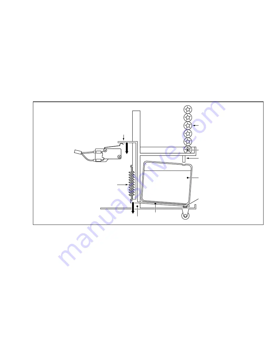
Operation of Drain Switch

6.

Drain Switch

The Classic Plus 14 is equipped with a drain tank switch.  When the drain tank accumulates approxi-
mately 4.0 gallons (15 liters) of condensate (water) in the drain tank, the drain tank switch sends a signal
to the microprocessor.  The microprocessor stops all operation of the unit and flashes the "Tank Full"
LED.

This system utilizes a .1 AMP, 250 VAC micro-switch for this function.  When drain water accumulates
approximately 4.0 gallons (15 liters) in the drain tank, the drain tank base plate, which is supported at its
fulcrum, is pushed down in the direction of the arrow as shown in the figure below.  When the drain tank
base plate is forced down, the top of the drain tank base plate turns off the contacts (1) – (2) of the micro
switch.  This causes the ground signal at the J103 connector of the control panel assembly to go open.
When the microprocessor detects this event, it turns the unit off and flashes the "Tank Full" LED.

When the drain tank is removed (or the drain tank is emptied), the top of the drain tank base plate
returns to its original position by the tension of the coil spring.  Then contacts (1) – (2) of the drain tank
switch close.  This provides a ground to the microprocessor through the J103 connector.  To re-start the
unit, press one of the fan mode buttons or the “Cool On/Off” button.  The unit will return to the previous
Temperature Set Point.

7.

Condensate Pump Kit (optional)

The Classic Plus 14 model comes standard with a drain tank, which collects the water that forms on the
evaporator during normal cooling operation. If the unit is required to operate continuously without
periodic emptying of this tank, a condensate pump may be needed. A condensate pump kit (CPK-3) is
available for the Classic Plus 14 model.

;;;

yyy

;;;

;;;

yyy

yyy

2

NC

C

1

DS2

DS1

To J103

DRAIN

SWITCH

DRAIN W

DRAIN WATER

BASE

PLATE

BASE

SPRING

DRAIN TUBE

EVAPORATOR

DRAIN TANK

FULCRUM

DRAIN PAN

TOP OF

BASE

PLATE

Summary of Contents for Classic Plus 14

Page 1: ...SERVICE MANUAL CLASSIC PLUS 14 ...

Page 2: ...ion or unit operation GENERAL PRECAUTIONS WARNINGS All electrical work if necessary should only be performed by qualified electrical personnel Repair to electrical components by non certified technicians may result in personal injury and or damage to the unit All electrical components replaced must be genuine MovinCool purchased from an authorized reseller When handling refrigerant always wear pro...

Page 3: ...ii ...

Page 4: ...F CONTENTS FOREWORD i DEFINITION OF TERMS i GENERAL PRECAUTIONS i TABLE OF CONTENTS iii GENERAL DESCRIPTION 1 CONSTRUCTION SPECIFICATIONS DATA 3 REFRIGERANT SYSTEM 9 ELECTRICAL SYSTEM 13 TROUBLESHOOTING REPAIR 19 ...

Page 5: ...iv ...

Page 6: ...lar areas or objects MovinCool Spot Cooling Systems have the following features 1 Compact Design The innovative design of MovinCool has resulted in one compact unit replacing the need for two separate units 2 Easy Transportation and Installation With the whole cooling system built into one compact unit MovinCool requires no piping and can be easily transported and installed 3 Energy Conservation M...

Page 7: ...GENERAL DESCRIPTION 2 ...

Page 8: ... SPECIFICATIONS DATA 3 Exhaust Air Duct Cool Air Duct Centrifugal Fan Housing for Condenser Fan Condenser Compressor Caster Control Box Capillary Tube Drain Switch Caster with Brake Construction of Classic Plus 14 ...

Page 9: ...ucts Evaporator Drain Tank Air Filter evaporator Front Panel Condenser Fan Side Panel Fan Motor Upper Panel Air Filter condenser Power Cord Condenser Air Filter condenser Compressor Capillary Tube Accumulator Casters Control Panel Evaporator Fan Control Box Base Panel ...

Page 10: ...hot air is blown out through the upper exhaust air duct Air taken in from the front face is cooled by the evaporator and then blown through the cool air duct which can be turned in any direction All the air inlets are equipped with filters while the exhaust air duct is protected by wire mesh 3 Compressor and Fans The compressor is hermetically sealed A two speed fan motor is used with two cen trif...

Page 11: ...r Hi speed 882 ft 3 min motor output 0 24 Kw High 0 19 Kw Low Compressor type rotary output 0 8 Kw refrigerant type R 22 refrigerant capacity 1 50 lbs 0 68 kg Safety Devices compressor overload relay included fan motor protector included anti freezing thermister included full drain tank switch included power interruption restart feature included time delay feature included Dimensions Weight W x D ...

Page 12: ...CONSTRUCTION SPECIFICATIONS DATA 7 Exterior Dimensions 16 6 12 5 19 4 25 6 20 6 2 8 2 2 21 1 26 5 3 8 41 5 37 7 ...

Page 13: ... 115V Cooling Capability x10 3 kcal h BTU h Cooling Capability Curve 115V 40 50 60 70 Relative Humidity of Inlet Air 6 10 8 8 14 4 10 18 0 12 21 6 14 25 2 Temperature C F Cool Air Temperature Difference Curve 25 77 30 86 35 95 40 104 30 86 25 77 35 95 40 104 45 113 Wet Bulb Temperature C F Dry Bulb Temperature C F Power Consumption kW 0 9 1 1 1 3 1 5 1 7 115V Power Consumption Curve ...

Page 14: ...ator Capillary tube Compressor Evaporator Condenser These parts are all connected by copper tubing All the connections have been brazed Compressor Condenser Evaporator Capillary Tube Accumulator REFRIGERANT FLOW COMPRESSOR ACCUMULATOR EVAPORATOR FAN MOTOR CONDENSER CAPILLARY TUBE Refrigerant System ...

Page 15: ...he cylinder The roller turns to compress the refrigerant in the space between the cylinder and eccentrically mounted roller The blade is in contact with the roller by means of spring force It partitions the space between the suction side and the discharge side to keep compressed refrigerant from returning to the suction side There is no suction valve The discharge valve is designed not to open unt...

Page 16: ...ine fins Heat is removed from the air being pulled across the evaporator by the centrifugal fan and the resulting cool air is expelled through the cool air ducts 6 Accumulator The accumulator is mounted on the suction gas piping between the evaporator and the compressor The accumulator separates the liquid refrigerant from the gas refrigerant letting only the gas refrigerant enter the compressor T...

Page 17: ... Condenser Inlet Pipe Evaporator Inlet Pipe Capillary Tube Connecting Tube condenser to capillary tube Condenser Outlet Pipe Compressor Suction Pipe insulated Connecting Pipe evaporator to compressor Evaporator Outlet Pipe Refrigerant System Piping ...

Page 18: ...lock CB Control Board RB Relay Board MF Fan Motor MC Compressor Motor CF Capacitor for Fan CC Capacitor for Compressor OLC Overload Relay of Compressor DS Full Drain Warning Switch THS Freeze Protection Thermistor RTH Room Thermistor SCP Short Circuit Plate G Ground J8 AUX1 Auxiliary Connector CPK3 AUX2 Auxiliary Connector Not Used Compressor Capacitor Fan Motor Capacitor Terminal Block Relay Boar...

Page 19: ...of the fan motor is con nected High Fan Mode When the High Fan Mode button on the control panel is pressed the micropro cessor turns on the button s LED and activates both the Fan On Relay and Fan Mode Relay This sends line voltage 115 VAC from the Fan On Relay to the N O Normally Open contacts of the Fan Mode Relay This output is connected to the J6 terminal Relay Board where the HIGH SPEED wire ...

Page 20: ...nd used for relay coil activation The 12 DC power is sent to the Control Panel Assembly where it is further reduced to 5 volts for the system logic The relay board also contains the DIP Switch The DIP Switch is used to change the Fan Mode operation from Stop to Operate and change the Set Point temperature display from F to C NOTE The relay board must be serviced as a complete assembly It has only ...

Page 21: ...e is an overcurrent situation or if abnormally high temperature builds up in the fan motor 4 Compressor Motor The compressor motor is a single phase motor It is contained within the same hous ing as the compressor Specifications Rated Voltage 115 volts Rated Output 800 Watts 5 Compressor Overload Relay An external compressor overload relay is used to protect the compressor motor This relay is moun...

Page 22: ...ly to go open When the microprocessor detects this event it turns the unit off and flashes the Tank Full LED When the drain tank is removed or the drain tank is emptied the top of the drain tank base plate returns to its original position by the tension of the coil spring Then contacts 1 2 of the drain tank switch close This provides a ground to the microprocessor through the J103 connector To re ...

Page 23: ...ed by relays on the relay board through a microprocessor in the control panel assembly The fan program in the microprocessor can be changed by a DIP Switch on the left side of the Relay Board located in the Control Box There are two settings A Cool to Stop When the DIP Switch is set to the Down or Stop position the microprocessor controls the fan motor using the same room temperature thermistor th...

Page 24: ... is obstructed Abnormal noise and or shaking Loose Compressor mounting nut Deformed or worn rubber grommet on the compressor mounting bolt Internal interference with other components Damaged or out of balance fan and scroll Insufficient Air Flow Clogged spine fins or Evaporator or Condenser running unit without filter s Fan mode switch on Low Defective fan motor Insufficient Cooling Environmental ...

Page 25: ...ing of the spine fins is necessary it is recommended that this service be performed by a qualified service technician 6 Examination of Operating Environment Operating environments will vary depending on location climate and surrounding conditions Installation location also can cause operational problems Consult your reseller concerning operational environment requirements 7 Inspection of Cooling C...

Page 26: ...rol panel 10 Front panel 2 Upper panel 11 Blower housing evaporator 3 Right side panel 12 Drain pan 4 Air filter 13 Left side panel 5 Blower housing condenser 14 Drain tank 6 Condenser fan 15 Service panel 7 Rear panel 16 Room thermistor 8 Drain Switch 17 Freeze thermistor 9 Caster 8 Disassembly ...

Page 27: ... of Service Panel Screws DISCONNECT DISCONNECT DISCONNECT Removal of Power Cord Screws Removal of Drain Tank A Remove Drain Tank B Remove 8 screws from the ducts then remove the 2 ducts C Remove 4 screws from the Service Panel D Remove 3 wires then remove the power cord 4 ...

Page 28: ...AND REPAIR 23 Removal of Back Panel Screws Removal of Top Panel Removal of Top Panel Screws 3 3 3 4 2 4 4 backside 2 2 E Remove remaining 13 screws and the back panel F Remove 14 screws from the Top Panel G Top Panel 4 ...

Page 29: ...l Board RB Relay Board MF Fan Motor MC Compressor Motor CF Capacitor for Fan CC Capacitor for Compressor OLC Overload Relay of Compressor DS Full Drain Warning Switch THS Freeze Protection Thermistor RTH Room Thermistor SCP Short Circuit Plate G Ground J8 AUX1 Auxiliary Connector CPK3 AUX2 Auxiliary Connector Not Used Compressor Capacitor Fan Motor Capacitor Terminal Block Relay Board Relay Board ...

Page 30: ...lay Board Fuse To Fan Motor High Speed Relay Board Ground not used To Fan Motor Low Speed To Terminal Block R Terminal Pin 2 Compressor Overload Relay To Terminal Block T Terminal DIP Switch Fan Mode Control Switch STOP OPERATE J104 J103 J106 J102 J101 J201 Jumper Drain Tank Switch NOT USED Freeze Thermistor Room Thermistor Main Wiring Harness Control Panel to Relay Board Connections to Relay Boar...

Page 31: ... AND REPAIR 26 Disassembly of Blower 10 Removal of Blower Assembly 1 Condenser fan 5 Partition plate 2 Blower housing condenser 6 Evaporator fan 3 Fan motor 7 Blower housing evaporator 4 Motor bracket 8 Air flow guide ...

Page 32: ...f Blower Housing A Loosen the set screw using an allen wrench and then remove the centrifugal fan B Remove the two 2 nuts on the inside of the housing in the locations shown A NUT C Remove two nuts and two screws as de picted Then remove the motor bracket together with the fan motor A NUT B SCREW ...

Page 33: ...rews 3 3 1 Removal of Right Side Panel Screws Removal of Fan Motor D Remove the centrifugal fan by loosening the set screw on the shaft Remove the fan motor by loosening A nuts E Remove 7 screws from Left Side Panel F Remove 7 screws from Right Side Panel 3 3 1 ...

Page 34: ...rews from Control Panel Assembly Left Stay I Disconnect the following connectors from the control board 1 Wire Harness Relay Board to Control Board J201 10 pin 2 Drain Tank Switch J103 2 pin 3 Room Temperature Thermistor J101 2 pin 4 Freeze Thermistor J102 2 pin NOTE Mark each of the 2 pin connectors with a different color marker to ensure the correct orienta tion when they are re connected ...

Page 35: ...nity This indicates that the capacitor is charging If the reading indicates infinity right away shorted or the ohmeter fails to move from 0Ω open replace the capacitor 12 Capacitance Tester Method Using a capacitance tester and the chart on page 15 test the capacitor for the value indicated If the value tested is not within 10 of indicated capacitance replace the capacitor Warning Properly dischar...

Page 36: ...5 Inspection of Compressor Motor Measure resistance across the terminals of the compressor motor Terminals at 77 F 25 C R C Approx 1 1Ω C S Approx 2 7Ω S R Approx 3 3Ω If the measured resistance value is not equal to these standard values replace the compressor The compressor uses an external overload relay For overload relay specification see chart on page 16 16 Inspection of Wiring Connection Re...

Page 37: ... slightly reducing flame Oxyacetylene is commonly used since it is easy to judge and adjust the condition of the flame Unlike gas welding a secondary flame is used for brazing It is necessary to preheat the base metal properly depending on the shape size or thermal conductivity of the brazed fitting The most important point in flame brazing is to bring the whole brazed fitting to a proper brazing ...

Page 38: ...t cycle to prevent oxidation NOTE Take care not to allow dirt water oil etc to enter into the pipe VERTICAL JOINT Heat the whole brazed fitting to a proper brazing temperature Bring the brazing filler metal into contact with the fitting so that the brazing filler metal starts flowing by itself Stop heating the fitting as soon as the brazing filler metal has flown into the clear ance Since the braz...

Page 39: ...onent can be replaced it is necessary to recover the refriger ant using standard recovery procedures and equipment 2 To prevent oxidation dry nitrogen should be conducted flow rate 1 liters min through the pinch off tube during any brazing operation 3 During any component replacement involving brazing shield nearby parts with a steel plate asbestos etc to protect them from the flame 1 Evaporator 2...

Page 40: ...se refrigerant to an open flame Never smoke while performing repairs especially when handling refrigerant Be careful the liquid refrigerant does not come in contact with the skin If liquid refrigerant strikes eye or skin Do not rub the eye or the skin Splash large quantities of cool water on the eye or the skin Apply clean petroleum jelly to the skin Go immediately to a physician or to a hospital ...

Page 41: ...stem for approximately 15 minutes 3 When the low pressure gauge indicates 750mmHg 30in Hg or larger turn off the vacuum pump and close the high and low pressure valves of the gauge manifold C Checking Vacuum 1 Leave the high pressure valve and the low pressure valve of the gauge manifold closed for five minutes or more and confirm that the gauge pointer does not return to zero 2 If the gauge point...

Page 42: ... Before checking for gas leaks fully confirm that there is nothing flammable in the area to cause an explosion or fire Contact of refrigerant with an open fire generates toxic gas E Evacuation Repeat 1 Close the valve of the refrigerant cylinder Then remove the charging hose green from the refrigerant cylinder and connect it to the refrigerant recovery machine NOTE Keep the high pressure valve and...

Page 43: ...rant to the specified amount Standard Amount of Refrigerant 1 50lbs 0 68kg If the system cannot be charged with the specified amount of refrigerant under this condition follow the steps below a Close the high pressure valve of manifold b Operate the refrigerant system c Slowly open the low pressure valve while observing the scale reading d When the scale reads the specified amount immediately clos...

Page 44: ... diagram 22 Compressor Mounting Mount the compressor on the frame using cushions steel collars spring washers plate washers and nuts 23 Blower Assembly Install blower fans for evaporator and con denser Tightening torque 10 84 2 17 lbf ft 150 30 kgf cm NOTE After reassembling the gap between blower fan and housing should be 0 06 inches 1 5 mm or more 24 Wiring Notice Secure the wires using clamps s...

Page 45: ... Plug TB Terminal Block CB Control Board RB Relay Board MF Fan Motor MC Compressor Motor CF Capacitor for Fan CC Capacitor for Compressor OLC Overload Relay of Compressor DS Full Drain Warning Switch THS Freeze Protection Thermistor RTH Room Thermistor SCP Short Circuit Plate G Ground J8 AUX1 Auxiliary Connector CPK3 AUX2 Auxiliary Connector Not Used 26 Schematic ...

Page 46: ...DSCA P N LA990009 0379 ...

Reviews: