background image

©2019 Moustache Model Works, LLC


31


20cc DHC

-

2 Beaver Instruction Manual


64.


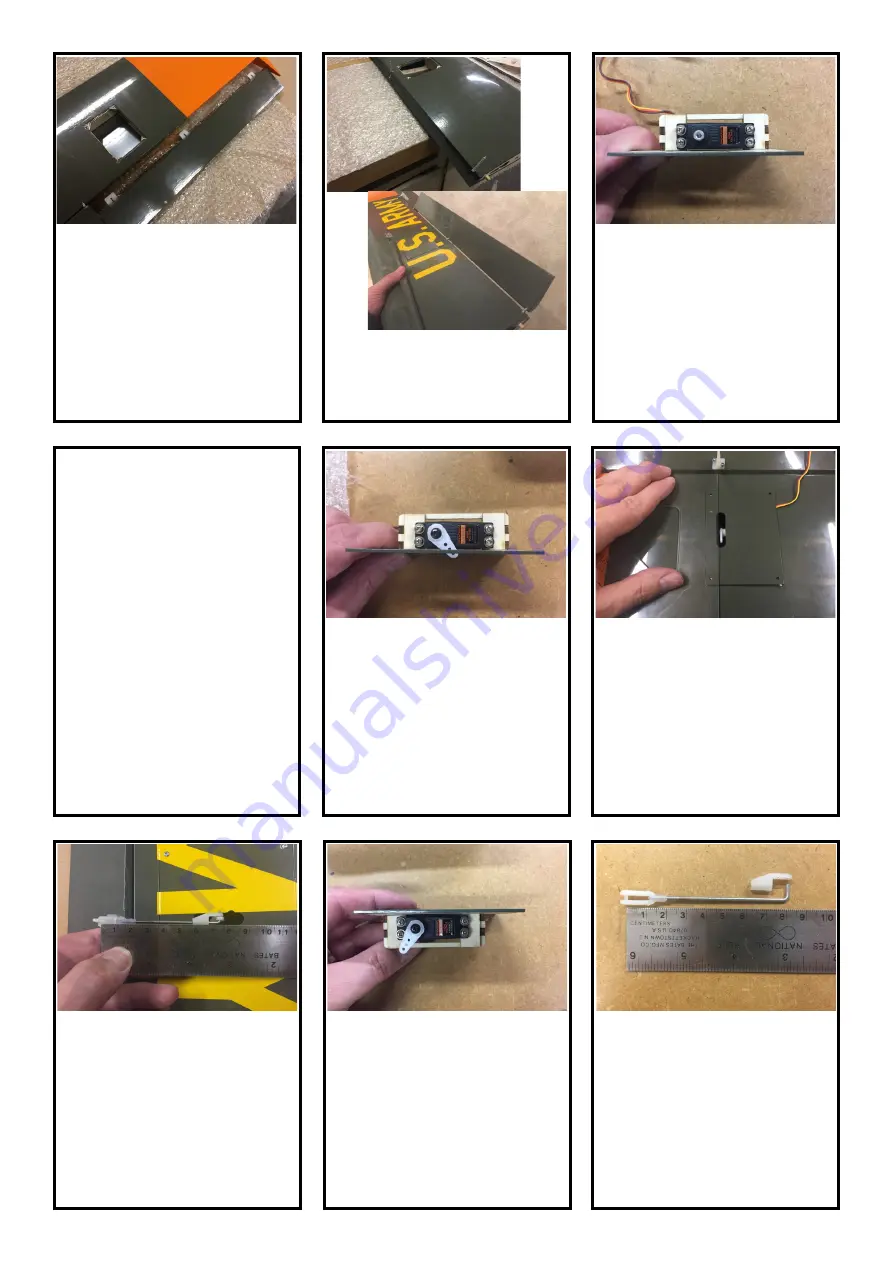
Install the 2mm pushrods using nylon 

clevises at the control horns and snap 

connectors at the servo arms.  Pushrod 

length will be about 2 

7/8” 

(73mm) from 

the clevis pin to the bend.


65.


As with the ailerons, prepare and install 

matching servo arms of 1/2 (13mm) 

length to the flap servos.  In the 

flaps 

up

” 

position, the servo arms should bias 

forward about 30°.


60.


Attach an 18

-

inch (45cm) servo exten-

sion to each aileron servo lead and 

secure using connector clips such as 

Spektrum part number SPMA3054 or 

dental floss wrapped around the con-

nectors.


61.


Select matching servo arms for the 

aileron servos with an arm length about  

1/2” 

(13mm) from the center to the 

outermost hole.  Cut off all the remain-

ing arms, and drill the outermost hole, if 

necessary, to fit the 2mm pushrods.


No Photo


62.


Ensure the aileron servos are centered 

by connecting them to the receiver, 

binding and powering

-

up.  Install the 

servo arms with a significant forward 

bias to the front to provide mechanical 

differential throw (more up deflection 

than down).


63.


Attach the aileron control horns to the 

ailerons using the supplied screws.  Drill 

pilot holes in the plywood using a 

1/16” 

(1.5mm) drill.


66.


Prepare the flap pushrods for installa-

tion using 2mm pushrods, nylon clevis-

es and snap connectors.  The pushrod 

length will be about 3 

3/16” 

(80mm) 

from the clevis pin to the bend.


56.


Cover the wings, ailerons, flaps, and 

hatches using your favorite covering 

film.  Hint:  a hot soldering iron works 

great to melt the holes for the round 

hinges, and for the cutouts in the aileron 

hatches.


57.


Attach the ailerons to the wings using 

the supplied CA hinges.


58.


Attach the flaps to the wings using the 

round hinges and epoxy.  Apply a bit of 

petroleum jelly to the hinge pin area to 

prevent their getting frozen stuck by 

some stray epoxy.


59.


Install the aileron and flap servos to the 

hatch mounts using the hardware that 

came with your servos.  Space the ser-

vos away from the hatch surface using 

a scrap piece of 1.0mm or 1.5mm ply-

wood.  Note the flap servo output shaft 

should be toward the forward edge of 

the hatch.


Summary of Contents for DHC-2 Beaver

Page 1: ...20cc DeHavilland Canada DHC 2 Beaver Instruction Manual Version 1 1 ...

Page 2: ...lectric Power System E flite Power 60 400Kv EFLM4060A Prop Adapter Power 46 52 60 EFLM1934 60A ESC Castle Creations Talon 90 recommended CSE010009700 5000mAh 6S 22 2V 30C LiPo Battery Connectors w 5mm bullets suggest XT90 or IC5 16 x 8E Propeller suggest APC16080E 1 inch Spinner Nut 8mm x 1 25mm P 47D 1 60 HAN279011 Gas Petrol Power System DLE 20 DLE 20RA DLEG0020 or DLEG0420 or equivalent Sulliva...

Page 3: ...r side depending on the aircraft you choose to model If you choose a single rear window the aft window bay is simply covered with the covering materi al If you choose the rectangular window s the pre cut forward window bay will need to separated from the fuselage side to accommodate Building Notes The 20cc Beaver was designed to minimize the need for plans during construction The tail surfaces and...

Page 4: ...e but it requires clear coat to be fuel proof If using a gasoline engine the electrical power system can be simplified by using an ignition battery elimi nator circuit or iBEC This simple component enables a single battery to power both the radio system and the ignition while also providing a transmitter switched ignition kill If HV capable servos are used a sin gle 2S Li Po battery can provide al...

Page 5: ...ng medium CA Laser etched lettering inside 5 With the Spar TE on the work bench and the ribs facing up look down on the stab and check for any twist If the stab is twisted hold a corrective twist in place while gluing each HS 2a to the Stab Doubler 6 Glue the remaining glue joints between the ribs and the Sub LEs and HS 9 10 Glue in the hinge reinforcement blocks as well as the HS 8 Doublers 3mm l...

Page 6: ...vator Skins Make sure the laser etching on the skins is on the inside surface Use the stab tip as semblies to aid positioning 18 Glue the ribs E 1 through E 6 to the leading edges Take care to center the ribs vertically on the LE As you did on the horizontal stabilizer use a scrap piece of lite ply with a 90 degree corner to ensure the ribs are perpendicular to the LE 12 Trim sand the sheeting flu...

Page 7: ...leva tors in place against the horizontal stabilizer and use a piece of scrap 2 5mm balsa as a spacer between the tip of the stabilizer and the inside edge of the elevator counter balance Mark the location then drill in straight with a 1 8 bit 29 Cut a relief groove in the trailing edge of the horizontal stab to provide clearance for the elevator control horn Also cut a bevel in the slot for the j...

Page 8: ...eleva tors at the elevator joiner 1 Remove the vertical stabilizer and dorsal fin parts from the laser cut sheets a VS 1 through VS 7 D 1 2 and 3 from 2 5mm balsa sheets 9 10 b Trailing edge hinge supports and rudder blocks from 6mm balsa c Dorsal spine and rudder tip from 1mm ply 43 Hinge the elevators to the stab using the supplied CA hinges Glue into the elevators first then use epoxy to glue t...

Page 9: ... to VS 4 5 and 6 14 Using that mark as a guide glue the Dorsal Spine LE 1 pieces 1 5mm balsa sheet 1 to the Dorsal Spine on both sides 6 Sand off the tip of the VS 8 tab that protrudes through VS 7 7 Glue D 1 in place 9 Remove the vertical stab skins from the 1 5mm laser cut sheets 10 Glue the skin parts together matching the edges that have the edges labeled for right and left skins 11 Lightly bl...

Page 10: ...R 1 R 6 from 2 5mm balsa c Tip core and rib from 1mm ply 17 Remove the Dorsal Skins from the 1 5mm laser cut sheets and assemble the same way as the vertical stab skins matching the edges with text labels for both left and right skins 18 Glue the Dorsal Skins in place 20 Sand the ends of the Vertical Stab lead ing edge to fit between the tabs on VS 6 and VS 7 NOTE the tabs on VS 6 and VS 7 are use...

Page 11: ...lling the skins sheeting 29 Remove the rudder skins from the 1 5mm balsa laser cut sheets 30 Glue the skin parts together matching the edges that have the edges labeled for right and left skins 31 Note skin alignment to 2nd leading edge 31 Glue one side of the rudder skin in place Use the tip plywood rib as a guide match the trailing edge of the skin to the trailing edge of the tip core Note the l...

Page 12: ...d cover with wax paper 2 Lay the leading edge sheeting 2 5mm x 3 x 48 in place over the plan and pin in place Do not trim the LE sheeting to width at this time 3 Do the same with the trailing edge sheeting 2 5mm x 3 4 x 48 4 Cut a piece 9 3 4 248mm long from the 2 5mm x 4 x 48 sheet for the cen ter section sheeting root end of the wing then trim it to 3 3 4 wide 95mm Glue and pin in place to the l...

Page 13: ... the root and tip ribs after assembly 16 Using a rib at the root one at the tip and one or two in the middle glue the bottom spar to the leading edge sheet ing the cap strips and the hatch fill ers NOTE that the spar overhangs the leading edge sheeting by 1 8 3mm to provide a better joint for the cap strips 17 Before gluing the ribs in place perform a dry assembly of the ribs upper spar Sub LE Ply...

Page 14: ...y flap hatch liner in place The narrow edge goes forward against the spar Don t glue in place until you test the fit the wing tube sleeve in place If the wing tube sleeve won t slide in over the top of the hatch liner then sand a slight relief in the hatch liner using a sanding drum on a rotary tool Glue the flap hatch liner in place 26 Glue the aileron hatch liner in place narrow edge forward 27 ...

Page 15: ...eading edge upper sheeting in place 2 5mm x 3 x 48 The trailing edge of the sheeting should be about 1 8 3mm forward of the aft edge of the spar to allow a slight shelf that will ease installation of the upper cap strips Apply medium or thick CA to all appropriate spots then position over the spar first and press into place Once the CA on the spar has grabbed roll the sheeting forward with your ha...

Page 16: ...from the end of the leading edge Carefully cut about half to two thirds of the way through the leading edge on this line using a razor saw This cut will enable the leading edge to easily bend for the tapered section between ribs R 1 and R 3 45 Sand the trailing edge lightly to ensure flatness to remove any overhang from the upper or lower sheeting 46 Fit the Tip Mounting Rib into the fiberglass wi...

Page 17: ...rod This hole needs to be about 5 16 6 8mm wide and about 3 8 9 10mm tall located al most to the upper trailing edge sheet ing See plans for spanwise location on the left wing the hole is centered 10 254mm from the root and on the right wing it s centered 11 298mm from the root You may want to wait until the flaps are finished before com pleting this step 50 Sand the upper surface of the triangle ...

Page 18: ...to place on the leading edge 10 Glue the upper skin in place keeping the flap flat on the building board 4 Glue the ribs into place 5 Glue the hinge support blocks into place at the ends of the flap Wait until the Flap Horn is installed to install the third support block 9 Sand the leading edge and trailing edge to match the contour of the ribs Note that the upper surface of the flap has a slight ...

Page 19: ...eading edge 5 Mark the location of the Aileron Horn Mount on the leading edge and cut a notch in the leading edge so it will fit over the horn mount 6 Glue the leading edge in place 9 Mark a centerline down the leading edge of the aileron then mark a bevel on each end to serve as a guide for carving and sanding the required bevel into the leading edge It can also help to draw spanwise lines on the...

Page 20: ...EADS 2 2 5 AND 3 WILL BE UNACCESSIBLE Use epoxy on the blind nuts and threadlock on the cap screws 4 The blind nuts close to the edge of bulkheads 2 5 and 3 will probably overhang the edge of the bulkheads Remove the float mounts from these locations file the blind nuts flush with the edge of the bulkheads and re install the float mounts 5 Glue the 2 5mm balsa sheeting help ers to the aft side of ...

Page 21: ...Doublers into place on the fuselage sides Use Bulkhead 3 to help get them properly positioned 13 Glue the 1mm ply door frames in place on the fuselage sides 14 Glue the 1mm ply door stiffeners in place at this time They are not need ed for the assembly yet but since they have been removed from the sheet installing them now will prevent dam aging them during storage Motor Box Assembly for Electric ...

Page 22: ...steps then drill the required engine mounting holes at a later point once the fuselage is more complete As drawn both sets of rails provide 2 of right thrust and 2 of down thrust For reference the face of the prop drive washer on the engine should be approximately 1 1 2 38mm forward of the motor box 15 Laminate the engine mount doublers onto the engine mounts using medium CA Pay attention to left ...

Page 23: ...ce in the Overhead Bulkhead then glue the Overhead Bulkhead into place 31 Install the wing tube sleeve It should be flush to the fuselage sides on both sides 32 Flip the fuselage upside down to install the Fuselage Bottom Apply a small shot of CA accelerator to the circled locations of the bottom sheet before assembly to help the CA grab as the sheeting is wrapped around the slightly curved Bulkhe...

Page 24: ...d Bulkhead needs to have a small relief cut for the fuselage side to set properly in place See photos Also note the top of Bulkhead 9 is slightly curved so you will need to form the top around that curve 38 Install the pre formed 2 5mm sheeting on the lower fuselage corners This sheeting has been formed to the proper radius at the factory to make building easier Start with the sections on the forw...

Page 25: ... a knife or a plane rough carve the pieces to be nearly flush with the sides and top b Second sand them to be fully flush with the sides and top c Third sand the radius which is more of an elliptical cross section than circular 43 Sand the top of the Canted Bulkhead flush with the fuselage sides at the stab saddle then sand a slight V shape in the same location when viewed from behind so the horiz...

Page 26: ...the interior color In both proto types we used a light gray acrylic paint from a local craft store 48 Carefully trim the windshield to fit the hatch A pair of curved body scissors sold by brands such as Dyna mite and Duratrax make this task much easier Take it slowly to achieve a proper fit a Start by removing the flange all around the wind shield b Tape in place and mark the trim line onto the wi...

Page 27: ...or the tail wheel steering cable guide tubes on the bottom of the fuselage approxi mately 1 30mm forward of the front tail wheel mounting hole and straddling the tail wheel mounting doubler The holes should go through the balsa and not the plywood 62 Install the 3mm cable guide tubes pok ing them through the holes and gluing with medium or thick CA Trim and sand flush with the outside surface then...

Page 28: ...he cowl to Bulkhead 1 70 Glue the cowl to the mounting tab assemblies using a mixture of epoxy and milled fiber Looking down from above the aft edge of the cowl will just cover the hatch bulkhead which should be visible through the clear windshield hatch From the side the aft edge of the cowl will be vertical Note that Bulkhead 2 angles backward about 2 5 so if you use it as a visual cue to aid al...

Page 29: ...81 Trim the edges to form a flange about 5 16 3 8 wide 8mm 10mm 82 Trim a notch forward of the triangle then file a semi round notch to clear the rudder torque rod Trim to length to match the beavertail 75 OPTIONAL If you re going to use the upper carb intake instead of the chin scoop assemble and install it at this time The carb intake is teardrop shaped when viewed from above while the oil coole...

Page 30: ...ke por tion fits properly in place f Glue the intake portion to the base portion 88 If powering your DHC 2 Beaver with a petrol engine or a glow engine a Drill holes in the separator bulk head for passing the throttle push rod and fuel lines through b Drill any required holes for mount ing the ignition likely on the motor box top c Seal the exposed plywood from Bulkhead 1 forward using epoxy finis...

Page 31: ...ervo arms with a significant forward bias to the front to provide mechanical differential throw more up deflection than down 63 Attach the aileron control horns to the ailerons using the supplied screws Drill pilot holes in the plywood using a 1 16 1 5mm drill 66 Prepare the flap pushrods for installa tion using 2mm pushrods nylon clevis es and snap connectors The pushrod length will be about 3 3 ...

Page 32: ... the elevators and rudder Use a hobby knife and a small round file 77 Assemble the struts to the fuselage wings adjusting the clevises to achieve the final proper length If you find any play in the wing tube wing joint we suggest you make the struts long enough to take up that play In this manner most of the wing loads will be absorbed by the wing tube 78 Once the final strut length is found use b...

Page 33: ... the rudder torque rod Check for symmetrical alignment with the wingtips in addition to sighting for level from front and be hind then glue in place using epoxy Once glued connect and adjust the elevator pushrod 11 Rough cut the seat parts leaving about a 6mm flange 12 Using a sharp pencil flat on the table mark the trim line for all the parts This is easy if you hold the pencil still and move the...

Page 34: ...etween them for a good glue joint Note that craft store acrylics don t stick well to the plastic use acrylics or enamels for plastic models 18 Glue the 2 5mm balsa seat supports into the seat bottoms using medium CA flush with the bottom edges 21 File a small flat on the tail wheel shaft to provide a seating surface for the control arm set screw 22 Assemble the tail wheel to the strut as shown We ...

Page 35: ...sand and or file the back of the aft servo cover to provide clearance for the pushrod and cable linkages 29 Trim the windows to about 1 8 3mm wide and glue in place in the fuselage and doors using Pacer Formula 560 Scrap balsa sticks can be used to help hold them in place while the glue dries 31 Install the handles onto the doors fac ing forward 24 Cut two lengths of the pull pull cable to about 4...

Page 36: ...e airplane completely and check cg CG has been tested between 2 and 3 70mm 83mm aft of the leading edge measured outboard of the taper at the root LE This equates to 28 33 of MAC CG is easiest to measure at the flap servo cover As CG moves aft the stall results in more wing drop but the Beaver recov ers quickly There is no one right cg The right cg is the one that yields the flight characteristics...

Page 37: ...nical differential by angling the aileron servo horns forward and electronic differential through computer transmitter programming Flying During takeoff apply throttle slowly and smoothly Hold a little up elevator from the beginning to keep the tail wheel on the ground and maintain steering control until the rudder sees enough airspeed to become effective especially on pavement Often this approach...

Page 38: ... LE 6mm x 13mm x 8 1 Cockpit Roof Support 5mm x 13mm x 48 4 Wing Spars Pine 10mm x 15 mm x 14 2 Wing Struts Airfoil Shape Bag 1 Wing Hardware Item Qty 2mm Pushrod for Flaps Ailerons 4 3mm Pushrod for Wing Struts 4 3mm Steel Clevis 4 3mm Clevis retaining nut 4 1 4 20 Wing Bolt Nylon thumb screw 2 1 4 20 Blind Nut for Wing Attach 2 2mm x 10mm Button head screw for servo hatches 16 2mm Nylon Clevis 4...

Page 39: ...or Mount gas or electric 4 4mm x 15mm Socket Head Cap screws for Electric Motor mounting 4 4mm x 25mm Socket Head Cap Screws for gas or glow Engine Mounting 4 4mm Split Washers for Engine Mounting Screws 4 4 40 x 3 8 Socket Head Cap Screws for Cowl attachment 4 4 40 Blind Nuts for cowl attachment 4 6mm Magnets Seat Attachments Doors 12 10mm Magnets Hatch 4 BAG 6 Long Parts Item Qty Cardboard Tube ...

Page 40: ...Moustache Model Works LLC PO Box 916 Mahomet IL 61853 www moustachemodelworks com ...

Reviews: