


Mx350_01a_oi_e.docx / Nov-19
page 21 / 72
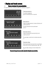
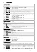
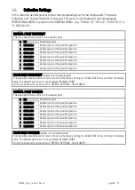
General Menu
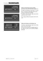
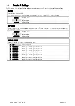
OPERATIONAL MODE
This parameter specifies the selected measuring function.
0 A SINGLE
Input A is the pulse input. (single-channel measurement)
1 A PULSE B DIR
Input A is the pulse input.
Input B determines the direction: for example, "LOW" = forward "HIGH" = backward
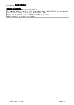
2 SUM A+B
Sum: counts impulses A + impulses B and frequency A + frequency B
3 DIF A-B
Difference: counts pulses A - pulses B and frequency A - frequency B
4 RATIO B/A
Ratio: Frequency and counter ratio of both channels (channel B / channel A).
Note: Interpretation of the result with 4 decimal places in the /- x.xxxx
5 %-DEVIA B/A
Deviation: percentage deviation from channel B to channel A.
Note: Interpretation of the result with 2 decimal places in the /- xxx.xx%
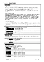
6 A/B 90 x1
Up / down counter for pulses with 2x90 ° offset
(simple edge evaluation x1)
7 A/B 90 x2
Up / down counter for pulses with 2x90 ° offset
(double edge evaluation x1)
8 A/B 90 x4
Up / down counter for pulses with 2x90 ° offset
(fourfold edge evaluation x1)
ENCODER PROPERTIES
(for MX350)
This parameter determines the characteristics of the pulse input for MX350.
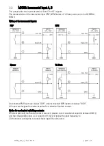
0 PNP
PNP (switch to +)
1 NPN
NPN (switch to -)
2 NAMUR
Connect sensor (–) to GND and sensor (+) to input (A or B)
3 TRI-STATE
Tri-State for push-pull encoders/ sensors
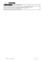
ENCODER PROPERTIES
(for MX355)
This parameter determines the characteristics of the pulse input for MX355.
0 RS422
RS422 standard
1 HTL DIFFERENTIAL HTL differential
2 HTL PNP
HTL PNP single ended (switch to +)
3 HTL NPN
HTL NPN single ended (switch to -)
ENCODER SUPPLY
(only for MX355 available)
This parameter defines the voltage of the auxiliary supply output (Aux-Out).
0 24VDC SUPPLY
24 VDC encoder supply
1 5VDC SUPPLY
5 VDC encoder supply
COUNTING DIRECTION
With this parameter the direction of rotation / direction of counting of the pulse inputs (input A and B) can be
reversed.
0 FOR. A / FOR. B
Direction of rotation / direction of counting of both pulse inputs (A and B) forward
1 REV. A / REV. B
Direction of rotation / direction of counting of both pulse inputs (A and B) reverse
2 FOR. A / REV. B
Direction of rotation / direction of counting input A forward and input B reverse
3 REV. A / FOR. B
Direction of rotation / direction of counting input A reverse and input B forward


