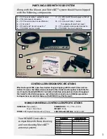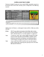
CONTROL CABLE PINOUT LEGEND
The Control Cable (9 conductor color-coded, 22AWG stranded) connects to
the Mount with a twist-lock connector, and is configured in the following
manner:
Additionally, the Mount is coil-wrapped inside with the following cables
and wire:
2-4 ea
-RG179 coax cables terminated at the LNB provide routing
between LNB and outputs. HD Series Mounts come standard
with 4, all other Mounts come with standard 2 or optional 4.
1 ea
-9 conductor cable, color-coded, 22AWG stranded. This cable
receives Control signals from the NOMAD Controller at the
twist-lock connection on the Mount, and distributes those
Control signals throughout the Mount as described above.
1 ea
-Green and White 22AWG stranded wires carry the positive
(white voltage) and negative (green ground) to the LED which
illuminate the dish face.
* Brown and Red are used to Skew the Dish. These wires control the Skew motors when directed by the NOMAD Controller. They are
used to control the skewable systems (MD500 / MD1000.2 / MHDTV / MSC60 / HD Series.) Applying 12 volt power directly to these wires
will skew the dish.
** Purple is for use on skewable systems to return counts, but it does not affect the operation of a non-skewable dish whether it is
connected or not connected.
Color Code Pin #
Mount Destination
Counts Per Degree
HD Series / Executive
Black
1
Motor, Azimuth Positive
Brown*
2
Motor, Azimuth/Skew Negative
Red*
3
Motor, Elevation/Skew Positive
Orange
4
Motor, Elevation Negative
Yellow
5
Sensor Count, Azimuth
5.700 / 3.408
Green
6
Sensor Count Ground, Azimuth/Elevation
Blue
7
Sensor Count, Elevation
8.530 / 5.034
White
8
LED Power
Purple**
9
Sensor Count, Skew
7.160 / 8.500
7
Summary of Contents for Nomad 2
Page 1: ...901 NOMAD IM Rev 08 16 08 NOMAD 2 NOMAD 3 OWNER S GUIDE ...
Page 3: ...1 INSTALLATION ...
Page 10: ...2 SETUP ...
Page 16: ...3 OPERATIONS ...
Page 20: ...4 TROUBLESHOOT ...
Page 23: ...5 UPGRADES ...
Page 29: ......


