background image

VIP2502W Wireless IPTV Receiver Installation Guide 

13

FCC Radiation Exposure Statement

This equipment complies with FCC radiation exposure limits set forth for an uncontrolled environment. This 

equipment should be installed and operated with minimum distance 20cm between the radiator and your body.
This transmitter must not be co-located or operating in conjunction with any other antenna or transmitter.
Firmware setting is not accessible by the end user.

Wireless LAN Information

The V1P2502W is a wireless network product that use Orthogonal freguency-division multiplexing (OFDM) radio 

technology. These products are designed to be interoperable with any other wireless OFDM type product that 

complies with:
• 

The IEEE 802.11 Standard on Wireless LANs (Revision A and Revision N), as defined and approved by the 
Institute of Electrical Electronics Engineers.

• 

The Wireless Fidelity (WiFi) certification as defined by the Wi-Fi Alliance.

Wireless LAN and your Health

The VIP2502W, like other radio devices, emit radio frequency electromagnetic energy, but operate within the 

guidelines found in radio frequency safety standards and recommendations. 

Restrictions on Use of Wireless Devices
I

n some situations or environments, the use of wireless devices may be restricted by the proprietor of the building 

or responsible representatives of the organization. For example, using wireless equipment in any environment 

where the risk of interference to other devices or services is perceived or identified as harmful.
If you are uncertain of the applicable policy for the use of wireless equipment in a specific organization or 

environment, you are encouraged to ask for authorization to use the device prior to turning on the equipment. 
The manufacturer is not responsible for any radio or television interference caused by unauthorized modification 

of the devices included with this product, or the substitution or attachment of connecting cables and equipment 

other than specified by the manufacturer. Correction of interference caused by such unauthorized modification, 

substitution, or attachment is the responsibility of the user.

FCC Declaration of Conformity

According to 47 CFR, Parts 2 and 15 for Class B Personal Computers and Peripherals; and/or CPU Boards and 

Power Supplies used with Class B Personal Computers, Motorola Mobility, LLC, 6450 Sequence Drive, San Diego, 

CA 92121, 1 800 225 9446, declares under sole responsibility that the product identifies with 47 CFR Part 2 and 15 of 

the FCC Rules as a Class B digital device. Each product marketed is identical to the representative unit tested and 

found to be compliant with the standards. Records maintained continue to reflect the equipment being produced 

can be expected to be within the variation accepted, due to quantity production and testing on a statistical basis as 

required by 47 CFR 2.909. Operation is subject to the following condition: This device must accept any interference 

received, including interference that may cause undesired operation. The above named party is responsible for 

ensuring that the equipment complies with the standards of 47 CFR, Paragraphs 15.101 to 15.109. 

Industry Canada statements:

This device complies with Industry Canada licence-exempt RSS standard(s). Operation is subject to the following 

two conditions: (1) this device may not cause interference, and (2) this device must accept any interference, 

including interference that may cause undesired operation of the device.
Cet appareil est conforme la norme d’Industrie Canada exempts de licence RSS. Son fonctionnement est soumis 

aux deux conditions suivantes: (1) cet appareil ne peut pas causer d’interférences, et (2) cet appareil doit accepter 

toute interférence, y compris les interférences qui peuvent causer un mauvais fonctionnement de l’appareil.

Caution:

The device for operation in the band 5150-5250 MHz is only for indoor use to reduce the potential for harmful 

interference to co-channel mobile satellite systems;
The maximum antenna gain permitted for devices in the bands 5250-5350 MHz and 5470-5725 MHz shall comply with 

the EIRP limit;
The maximum antenna gain permitted for devices in the band 5725-5825 MHz shall comply with the EIRP limits 

specified for point-to-point and non point-to-point operation as appropriate.
High-power radars are allocated as primary users (i.e. priority users) of the bands 5250-5350 MHz and 5650-5850 

MHz and that these radars could cause interference and/or damage to LE-LAN devices
Les dispositifs fonctionnant dans la bande 5 150-5 250 MHz sont réservés uniquement pour une utilisation à 

l’intérieur afin de réduire les risques de brouillage préjudiciable aux systèmes de satellites mobiles utilisant les 

mêmes canaux;

Summary of Contents for VIP2502W

Page 1: ...VIP2502W Wireless IPTV Receiver Installation Guide ...

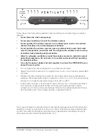
Page 2: ...ication and supply rating are provided on the label found on the bottom of the unit IMPORTANT SAFETY INSTRUCTIONS Read these instructions Keep these instructions Heed all warnings Follow all instructions Do not use this apparatus near water Clean only with a dry cloth Do not block any ventilation openings Install according to the manufacturer s instructions Do not install near any heat sources suc...

Page 3: ...to your home AC power outlet Do not plug the AC power adapter into a switched power outlet Always transport the receiver in its original factory carton or in an equally well padded container Whether installed or being transported do not expose the receiver to temperature extremes The temperature range for operation is from 0 to 40 C The non operating transport or storage temperature range is from ...

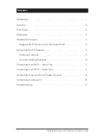
Page 4: ... 3 Wireless Connection 4 Register the TV Receiver with the Access Point 4 Connecting Your TV Receiver 5 Connection Options 5 Common Cabling Examples 6 Connecting to an HDTV Video Only 7 Connecting to an HDTV Audio Only 8 Connecting Audio to a Home Theater Receiver 9 Connecting to a Stereo TV 10 Troubleshooting 11 ...

Page 5: ...HD capable TV A direct digital connection to consumer audio and video devices through multiple interfaces Video on Demand VoD Commercial free CD quality music This installation manual introduces the basic features outlines important safeguards and provides options for integrating your wireless receiver into your entertainment system Please take a few moments to read through this manual Its configu...

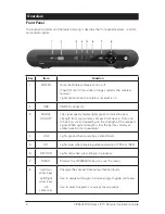
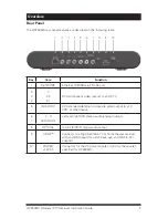
Page 6: ... to indicate signal strength from your wireless Access Point device From one to five bars are lit depending on the strength of the received signal When signal strength is low the bar may display as amber weak or red unusable 4 LINK Lights green when receiving a video stream 5 HD Lights blue when receiving video resolution of 720p or 1080i 6 RECORD Lights red when a recording is in progress 7 MENU ...

Page 7: ...to an HDTV 5 VIDEO OUT RCA standard definition composite video output to a TV VCR or other device 6 7 L R AUDIO OUT Left and right RCA stereo audio analog outputs 8 OPTICAL Toslink S PDIF digital audio output 9 HDMI Connects to a High Definition TV or home theater receiver with an HDMI input for a DVI input use an HDMI to DVI adapter 10 POWER 12 VDC Connector for the DC power adapter Use only the ...

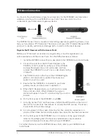
Page 8: ...ct the VIP2502W to your TV set as described starting on page 5 3 The POWER button on the front of the VIP2502W lights green to indicate power is applied Ensure power is applied to your TV as well 4 Ensure that the VAP2500 is connected to your home gateway device and that power is applied to it 5 When the TV Receiver starts up it will look for a signal from an Access Point When it detects the signa...

Page 9: ...s higher video quality than component video If your HDTV has an HDMI input use the HDMI connector HDMI provides both digital video and digital audio including Dolby Digital 5 1 Surround Sound No other connections are necessary If your HDTV has a DVI input you can use an HDMI to DVI converter cable to connect to the VIP2502W HDMI connector Use a cable with an HDMI connector on one end and a DVI con...

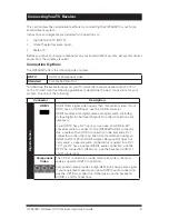
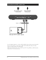
Page 10: ... video signal If your equipment supports an optical S PDIF audio connection use the OPTICAL connection Otherwise use the baseband AUDIO L and R connections Common Cabling Examples The following cabling diagrams illustrate common sample audio video A V connections When connecting other components to your TV Receiver refer to the other component installation manuals for additional connection informa...

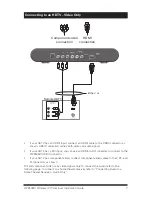
Page 11: ...ector as shown HDMI connection carries both video and audio signals If your HDTV has a DVI input you can use an HDMI to DVI converter to connect to the VIP2502W HDMI connector If your HDTV has component video connect component video cables to the Y Pb and Pr connectors as shown DVI and component video carry video signals only To connect the audio refer to the following page To connect to a home th...

Page 12: ...r Optical S PDIF connection Baseband audio connection If your equipment supports it use the OPTICAL S PDIF output Otherwise use the AUDIO OUT L and R connectors In most cases S PDIF offers better audio quality including support for Dolby Digital 5 1 Surround Sound HDMI carries video and audio If you connect your HDTV using HDMI no additional audio connections to the TV are necessary ...

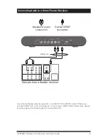
Page 13: ...R OUTPUT SPEAKER CONNECTORS COAX VIDEO S VIDEO R DVD CABLE TV VIDEO 2 IN OUT VCR AUDIO VIDEO L VIDEO S VIDEO OPTICAL Sample home theater receiver Either or If your home theater receiver supports it use the OPTICAL S PDIF output Otherwise use the AUDIO OUT L and R connectors In most cases S PDIF offers better audio quality including support for Dolby Digital 5 1 Surround Sound ...

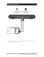
Page 14: ...ting to a StereoTV HDMI CABLE ANTENNA IN INPUT S VIDEO VIDEO AUDIO LEFT AUDIO RIGHT Sample stereoTV Composite video connection Baseband audio connection This video connection method does not support HD video For more information see Connecting an HDTV Video Only ...

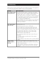
Page 15: ...ote control may be depleted The remote control does not work Verify that the TV is on Verify that the remote control is on STB mode Verify that there are no obstructions between the remote control and the wireless receiver Aim the remote control directly at the wireless receiver front panel not the TV or VCR The angle between the remote control and the wireless receiver may be too large Stand in f...

Page 16: ...ssion Radio andTelevision Interference Statement for a Class B Device This equipment has been tested and found to comply with the limits for a Class B digital device pursuant to part 15 of the FCC Rules These limits are designed to provide reasonable protection against harmful interference in the residential installation This equipment generates uses and can radiate radio frequency energy and if n...

Page 17: ...ards and Power Supplies used with Class B Personal Computers Motorola Mobility LLC 6450 Sequence Drive San Diego CA 92121 1 800 225 9446 declares under sole responsibility that the product identifies with 47 CFR Part 2 and 15 of the FCC Rules as a Class B digital device Each product marketed is identical to the representative unit tested and found to be compliant with the standards Records maintai...

Page 18: ...WARE PROVIDED WITH MOTOROLA S IP VIDEO RECEIVER OR HOME THEATER SYSTEM EACH SHALL BE REFERRED TO IN THIS LICENSE AS A RECEIVER BY USING THE RECEIVER AND OR USING ANY OF THE SOFTWARE YOU INDICATE YOUR ACCEPTANCE OF EACH OF THE TERMS OF THIS LICENSE UPON ACCEPTANCE THIS LICENSE WILL BE A LEGALLY BINDING AGREEMENT BETWEEN YOU AND MOTOROLA THE TERMS OF THIS LICENSE APPLY TO YOU AND TO ANY SUBSEQUENT U...

Page 19: ...nded for use in on line control of aircraft air traffic aircraft navigation or aircraft communications or in design construction operation or maintenance of any nuclear facility MOTOROLA AND ITS THIRD PARTY LICENSORS DISCLAIM ANY EXPRESS OR IMPLIED WARRANTY OF FITNESS FOR SUCH USES YOU REPRESENT AND WARRANT THAT YOU SHALL NOT USE THE PRODUCT FOR SUCH PURPOSES Title to this Software including the o...

Page 20: ...591850 001 b 05 13 Visit our website at www motorola com ...

Reviews: