background image

5 - 2

SE3300 Integration Guide

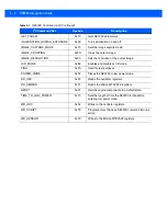
GET_PARAM

0x70

Gets SE3300 parameters.

ILLUMINATION_DURING_EXPOSURE

0x59

Turns illumination on and off.

IMAGE_CAPTURE_MODE

0x73

Sets the image capture mode.

IMAGE_CROPPING

0x5D

Crops the output image.

IMAGE_RESOLUTION

0x5C

Sets the resolution of the output image.

LCD_MODE

0x82

Enables and disables LCD mode.

PING

0x7A

Used for test purposes.

POWER_MODE

0x5F

Places the SE3300 in low power mode.

RD_OSC

0x53

Reads the oscillator registers.

RD_SENSOR

0x51

Reads the Micron MT9V022 registers.

RESET

0x57

Returns engine components to a default state.

TIME_TO_LOW_POWER

0x75

Sets the length of time the SE3300 is idle before 
entering low power mode.

WR_OSC

0x52

Writes to the oscillator registers.

WR_SCRIPT

0x76

Programs more than one SE3300 command into one 
script.

WR_SENSOR

0x50

Writes to the Micron MT9V022 registers.

Table 5-1    

SE3300 Command List (Continued)

I

2

C Command Set

Opcode

Description

Summary of Contents for SE3300

Page 1: ...SE3300 INTEGRATION GUIDE ...

Page 2: ......

Page 3: ...SE3300 INTEGRATION GUIDE 72E 148589 01 Revision 8 September 2011 ...

Page 4: ...ram in a network without written permission from Motorola The user agrees to maintain Motorola s copyright notice on the licensed programs delivered hereunder and to include the same on any authorized copies it makes in whole or in part The user agrees not to decompile disassemble decode or reverse engineer any licensed program delivered to the user or any portion thereof Motorola reserves the rig...

Page 5: ...iii Revision History Changes to the original guide are listed below Change Date Description 01 Rev A 9 2011 Initial release ...

Page 6: ...iv SE3300 Integration Guide ...

Page 7: ...3 Illumination System 1 3 Illumination Control 1 3 Frame Rate Control 1 3 Chapter 2 Installation Introduction 2 1 General Information 2 1 Electrostatic Discharge ESD 2 1 Environment 2 1 Power Supply Noise 2 1 Thermal Considerations 2 2 External Optics Aiming LED Lens and Imaging Lens 2 2 Image and Document Capture 2 2 Regulatory Information 2 2 Mounting 2 3 Housing Design 2 4 Optical 2 4 Positioni...

Page 8: ...hapter 5 Control Interface Introduction 5 1 Command List 5 1 Transactions 5 3 I2C Command Format 5 3 I2C Response Format 5 3 Command Checksum 5 4 Response Status Code 5 4 Command Descriptions 5 5 ACQUISITION 0x58 5 5 ACQUISITION_MODE 0x5B 5 5 AIM 0x55 5 5 AIM_BLINK_RATE 0xF4 5 5 AIM_DURING_EXPOSURE 0x56 5 5 AIM_POWER 0xF3 5 6 AUTO_POWER_REDUCTION 0x74 5 6 ENTER_BOOTLOADER 0x91 5 6 EXEC_INLINE 0x83...

Page 9: ...OSC 0x52 5 9 WR_SCRIPT 0x76 5 9 WR_SENSOR 0x50 5 9 Command Response Formats 5 10 Chapter 6 Application Notes Introduction 6 1 Image Acquisition 6 1 Output Data Format 6 2 Output Data Timing 6 2 Recommended Procedures 6 4 Normal Decode Mode 6 4 Snapshot Mode 6 9 Recommendations 6 9 Power Mode 6 9 Scripts 6 9 Appendix A Register Settings ...

Page 10: ...viii SE3300 Integration Guide ...

Page 11: ...unding ESD and environmental considerations Chapter 3 Specifications provides technical specifications for the engine including decode ranges Chapter 4 Electrical Interface includes signal information and connector drawings Chapter 5 Control Interface describes the SE3300 bi directional control interface Chapter 6 Application Notes describes SE3300 operating modes Appendix A Register Settings prov...

Page 12: ...re 9398 39340011 pdf Aptina MT9V022 mono Wide VGA CMOS Digital Image Sensor Datasheet http www aptina com Molex connector specification 54809 Series http www molex com Kyocera connector specification 6283 Series http global kyocera com For the latest version of this guide and all guides go to http supportcentral motorola com NOTE This symbol indicates something of special interest or importance to...

Page 13: ...on number Motorola responds to calls by e mail telephone or fax within the time limits set forth in support agreements If your problem cannot be solved by Motorola Solutions support you may need to return your equipment for servicing and will be given specific directions Motorola is not responsible for any damages incurred during shipment if the approved shipping container is not used Shipping the...

Page 14: ...xii SE3300 Integration Guide ...

Page 15: ...The SE3300 uses LED aiming and illumination and is available in the following three models to accommodate working range or more precise focusing in high density bar code decoding or digital picture taking SE3300SR Standard working range SE3300WA Wide angle SE3300HD High density CAUTION This device emits IEC Class 1M LED light Do not view directly with optical instruments ...

Page 16: ...re 4 5 on page 4 6 An amber LED and associated optics generate an aiming pattern and dual high output LEDs provide illumination for the imager under virtually any lighting condition The aiming subsystem illumination system and frame rate are under dynamic software control The primary component of the SE3300 imager is a 1 3 format CMOS wide VGA 752 H x 480 V monochrome digital image sensor The CMOS...

Page 17: ...bar code decoding Illumination System The illumination system consists of two high output red LEDs 625 nm and a sophisticated drive system that allows image capture and decoding throughout a full range of lighting conditions total darkness to full sunlight Illumination Control The SE3300 can capture images with the illumination subsystem turned on or off accommodating images that are close to the ...

Page 18: ...1 4 SE3300 Integration Guide ...

Page 19: ...lumination system LEDs Dust and other external contaminants eventually degrade engine performance Motorola does not guarantee performance of the SE3300 when used in an exposed application Power Supply Noise For reliable operation a low noise power supply is required Pay proper attention to power supply quality and testing to ensure the best possible performance from the SE3300 In bar code applicat...

Page 20: ...h both aiming and illumination enabled full time is highly uncommon In typical decoding and image capture applications any rise in engine temperature is minimal External Optics Aiming LED Lens and Imaging Lens Do not subject external optical components on the SE3300 engine to any external force Do not hold the engine by an external optical component This can place excessive stress in the mechanica...

Page 21: ...rews with a maximum engagement depth of 5 5 mm Recommended mounting screw torque is 3 5 in lb Figure 2 1 SE3300 Mounting Diagram NOTE Mounting the SE3300 in a non upright position results in images rotated accordingly in snapshot mode Notes Unless otherwise specified Holes marked B are mounting holes Holes marked A and slots marked C are imager engine locating aides This is a reference drawing and...

Page 22: ...y designed enclosure or improper selection of window material can affect the performance of the SE3300 Positioning the Exit Window Position the window so that illumination system light reflected off the inside of the window is not reflected back into the engine see Recommended Exit Window Information on page 2 9 If the designed enclosure cannot accommodate the recommended window angle contact Moto...

Page 23: ... sensitivity to the moving target If using plastic is necessary the following two materials are available Cell Cast Acrylic ASTM PMMA Cell Cast Acrylic or Poly methyl Methacrylic PMMA is fabricated by casting acrylic between two precision sheets of glass This material has very good optical quality reasonably good impact resistance and low initial cost but is relatively soft and susceptible to atta...

Page 24: ...abrasion and scratch resistance See Table 2 3 A Word About Coatings If using an anti reflective AR coating the specifications in Table 2 4 apply Polysiloxane coating is not required Recess the exit window to minimize scratches and digs Table 2 3 Taber Test Results on Common Exit Window Materials Sample Haze 100 cycles Haze 500 cycles Abrasion Resistance Chemically Tempered Float Glass 1 20 1 50 Be...

Page 25: ...Installation 2 7 Optical Path and Exit Window Figure 2 2 SE3300 Optical Path See Table 2 1 See Table 2 1 See Table 2 1 See Table 2 1 See Table 2 1 See Table 2 1 See Table 2 1 ...

Page 26: ...2 8 SE3300 Integration Guide Figure 2 3 SE3300 Illumination and Aiming Path See Table 2 5 See Table 2 5 ...

Page 27: ...Tilt Angle c Required for Integration Engine Model Part Number Window Specification Distance b Front Surface of Chassis to Exit Window 6 mm 11 mm 16 mm 21 mm 26 mm 31 mm SE3300WA Non coated 34o 33o 25o 24o 23o 22o Anti reflective AR coated one side facing engine 32o 31o 25o 24o 23o 22o AR coated two sides 18o 18o 18o 18o 18o 18o SE3300SR SE3300HD Non coated 31o 28o 27o 21o 20o 19o AR coated one si...

Page 28: ...s Integration tolerances are not included Ensure the window size is large enough to cover the imaging field of view and usable illumination volume specified in Figure 2 2 and Figure 2 3 plus mounting tolerances of the window relative to the engine ...

Page 29: ...M 3 3VDC at 23 C Low Power Idle Image Acquisition Illumination Enabled Maximum Operating Current aiming on during exposure illumination enabled SE3300SR SE3300HD 500 μA 18 mA 80 mA 250 mA 275 mA SE3300WA 500 μA 18 mA 80 mA 200 mA 250 mA Maximum Sensor Power Supply Noise at 23 C 100 mVp p 3 3 V 10 Hz 100 kHz for decoding 30 mVp p 3 3 V 10 Hz 100 kHz for image capture For better image quality in ima...

Page 30: ...izontal 24 9º vertical Focusing Distance from Front of Engine SR WA HD 5 2 in 13 3 cm 4 5 in 11 5 cm 2 7 in 6 9 cm Aiming Element Dot Optical Power 0 19 mW typical Illumination System LEDs Pattern Angle 625 5 nm dominant wavelength 60º x 40º at 80 center intensity Shock 2000 G 5 applied via any mounting surface at 0º C 20º C and 50º C for a period of 0 85 0 05 msec Vibration Unpowered SE3300 withs...

Page 31: ...nsions 17 00 mm H x 30 00 mm W x 17 25 mm D 0 669 in H x 1 181 in W x 0 679 in D Weight 6 1 grams 0 22 oz Electrical Interface 21 pin 0 3 mm pitch ZIF connector See Chapter 4 Electrical Interface for more information Table 3 1 SE3300 Technical Specifications Continued Item Description NOTE Environmental and or tolerance parameters are not cumulative Motorola recommends a thermal analysis if the ap...

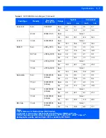
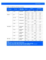
Page 32: ...Note 1 Far 14 3 36 3 13 2 33 6 20 mil 123 Near Note 1 Far 25 8 65 6 24 0 60 9 60 UPC 7 8 mil 12345678905 Near 1 1 2 9 1 5 3 8 Far 10 5 26 6 9 5 24 2 80 UPC 10 4 mil 12345678905 Near 1 5 3 8 2 2 5 7 Far 13 3 33 8 12 3 31 1 100 UPC 13 mil 12345678905 Near 1 9 4 9 2 8 7 2 Far 17 5 44 4 16 8 42 6 200 UPC 26 mil 13579256809 Near 3 6 9 1 4 5 11 4 Far 28 9 73 4 27 1 68 8 Notes 1 Near distance is Field of...

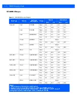
Page 33: ...s Near 3 4 8 6 3 7 9 5 Far 4 3 10 9 3 5 8 8 7 5 mil 1234567890 6 times Near 2 4 6 1 2 9 7 4 Far 6 8 17 3 6 2 15 8 10 mil 1234567890 6 times Near Note 1 Far 8 9 22 7 8 3 21 0 15 mil 1234567890 6 times Near Note 1 Far 12 1 30 6 11 5 29 3 QR Code 10 mil 1234567890 6 times Near Note 1 Far 7 4 18 8 6 9 17 7 Table 3 2 SE3300SR Decode Ranges Continued Code Type Density Bar Code Description Range Typical ...

Page 34: ...16 5 42 0 60 UPC 7 8 mil 12345678905 Near 1 2 3 1 1 7 4 4 Far 9 1 23 2 8 0 20 3 80 UPC 10 4 mil 12345678905 Near 1 4 3 4 2 0 5 0 Far 11 4 28 9 9 8 24 8 100 UPC 13 mil 12345678905 Near 1 6 4 2 2 6 6 5 Far 13 2 33 5 11 0 27 9 200 UPC 26 mil 13579256809 Near 3 1 7 9 4 2 10 6 Far 19 5 49 5 16 3 41 3 Code 128 5 mil C128 MOT Near 2 1 5 2 2 5 6 4 Far 5 4 13 6 4 7 11 8 20 mil 20MIL C128 Near Note 1 Far 16...

Page 35: ...0 6 times Near 2 3 5 7 2 7 6 8 Far 6 1 15 4 5 6 14 2 10 mil 1234567890 6 times Near Note 1 Far 7 6 19 3 6 6 16 8 15 mil 1234567890 6 times Near Note 1 Far 10 1 25 6 8 5 21 6 QR Code 10 mil 1234567890 6 times Near Note 1 Far 6 5 16 4 6 0 15 1 Table 3 3 SE3300WA Decode Ranges Continued Code Type Density Bar Code Description Range Typical Guaranteed Inch cm Inch cm Notes 1 Near distance is Field of V...

Page 36: ... 10 2 26 0 60 UPC 7 8 mil 12345678905 Near 1 0 2 7 1 5 3 9 Far 6 4 16 3 5 3 13 5 80 UPC 10 4 mil 12345678905 Near 1 5 3 9 2 2 5 6 Far 7 5 19 1 6 2 15 7 100 UPC 13 mil 12345678905 Near 1 9 4 9 2 9 7 4 Far 8 7 22 0 6 7 17 0 200 UPC 26 mil 13579256809 Near 3 6 9 1 4 3 11 0 Far 12 6 32 0 10 8 27 3 Code 128 5 mil C128 MOT Near 1 2 3 1 1 8 4 6 Far 5 4 13 7 4 4 11 3 20 mil 20MIL C128 Near Note 1 Far 10 8...

Page 37: ...0 3 3 3 8 4 7 5 mil 1234567890 6 times Near 1 4 3 6 2 1 5 3 Far 4 7 12 1 3 9 10 0 10 mil 1234567890 6 times Near Note 1 Far 5 7 14 4 4 9 12 4 15 mil 1234567890 6 times Near Note 1 Far 6 9 17 4 5 9 15 1 QR Code 10 mil 1234567890 6 times Near Note 1 Far 4 9 12 5 4 1 10 5 Table 3 4 SE3300HD Decode Ranges Continued Code Type Density Bar Code Description Range Typical Guaranteed Inch cm Inch cm Notes 1...

Page 38: ...3 10 SE3300 Integration Guide ...

Page 39: ...2 C Clock 4 I2C_DATA I O I2 C Data 5 VSYNC O Vertical sync 6 PIX_DATA_7 O Sensor Pixel Data MSB 7 PIX_DATA_6 O Sensor Pixel Data 8 PIX_DATA_5 O Sensor Pixel Data 9 PIX_DATA_4 O Sensor Pixel Data 10 PIX_DATA_3 O Sensor Pixel Data 11 PIX_DATA_2 O Sensor Pixel Data 12 PIX_DATA_1 O Sensor Pixel Data 13 PIX_DATA_0 O Sensor Pixel Data LSB 14 EXT_ILLUM_EN O External illumination trigger 15 VCC_SENSOR WVG...

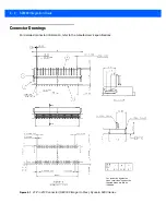
Page 40: ...gs For detailed connector information refer to the manufacturer s specifications Figure 4 1 21 Pin ZIF Connector SE3300 Imager to Flex Kyocera 6283 Series For protection against an open circuit in being bent the tapered areas are laid as indicated ...

Page 41: ...Electrical Interface 4 3 Figure 4 2 21 Pin ZIF Connector SE3300 Imager to Flex Kyocera 6283 Series continued ...

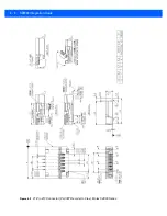
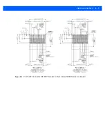
Page 42: ...4 4 SE3300 Integration Guide Figure 4 3 21 Pin ZIF Connector PL3307 Decoder to Flex Molex 54809 Series ...

Page 43: ...Electrical Interface 4 5 Figure 4 4 21 Pin ZIF Connector PL3307 Decoder to Flex Molex 54809 Series continued ...

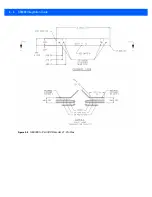
Page 44: ...4 6 SE3300 Integration Guide Figure 4 5 SE3300 to PL33XX Decoder 21 Pin Flex ...

Page 45: ...put ACQUISITION_MODE 0x5B Optimizes the SE3300 for a specific operation AIM 0x55 Turns the aim pattern on and off AIM_BLINK_RATE 0xF4 Controls the blink rate of the aim pattern AIM_DURING_EXPOSURE 0x56 Captures the aim pattern in the image AIM_POWER 0xF3 Controls the brightness of the aim pattern AUTO_POWER_REDUCTION 0x74 Places the SE3300 in a low power state when idle ENTER_BOOTLOADER 0x91 Enter...

Page 46: ...st purposes POWER_MODE 0x5F Places the SE3300 in low power mode RD_OSC 0x53 Reads the oscillator registers RD_SENSOR 0x51 Reads the Micron MT9V022 registers RESET 0x57 Returns engine components to a default state TIME_TO_LOW_POWER 0x75 Sets the length of time the SE3300 is idle before entering low power mode WR_OSC 0x52 Writes to the oscillator registers WR_SCRIPT 0x76 Programs more than one SE330...

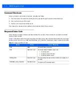
Page 47: ...ed by the I2 C specification SLA W is 0xB8 Slave Addr Write Op or Slave Address is 0x5C or 0xB8 after shifting into 7 MSBs Write Op is 0x00 Opcode is 1 byte from the SE3300 Command Op column in Table 5 3 on page 5 10 SE3300 Cmd Data is from the SE3300 Command Data column in Table 5 3 on page 5 10 This can be NULL Checksum is a 1 byte checksum of the SE3300 Cmd Data bytes See Command Checksum on pa...

Page 48: ...of the command A successful command returns an ACK or 0x80 Table 5 2 lists status codes for single errors Note that these error codes are bit positions within the status byte and two errors can occur e g NAK and INTERNAL_I2C_FAILURE resulting in values not listed in this table Table 5 2 Response Status Codes Status Value Cause Meaning ACK 0x80 Command was successful NAK 0x82 Bit 1 set Command fail...

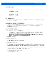
Page 49: ...it turns aiming on upon the next ACQUISITION Start command AIM_BLINK_RATE 0xF4 Controls the blink rate of the aiming pattern The aiming pattern only blinks when AIM is enabled The default is Always On This command takes two parameters Byte 1 Number of frames the aiming pattern remains on 0 Always On Byte 2 Number of frames the aiming pattern is off Blink rate times depend on the frame rate for exa...

Page 50: ...d the SE3300 does not automatically enter low power mode ENTER_BOOTLOADER 0x91 Enters bootloader mode which changes the SE3300 protocol so that it no longer supports this command set Bootloader mode is required for firmware update EXEC_INLINE 0x83 Executes more than one command inline without first writing it to the engine This is helpful for scripts that don t require executing more than once Exa...

Page 51: ... Start command IMAGE_CAPTURE_MODE 0x73 Sets image capture mode to one of the following Continuous 0x00 an ACQUISITION Start command results in continuous image frames one right after another until you issue the ACQUISITION Stop command Snapshot 0x01 an ACQUISITION Start command results in only one image frame Issue another ACQUISITION Start command to acquire another image frame The default is Con...

Page 52: ...ER_MODE 0x5F Changes the SE3300 s power mode Although this command offers a Full Power mode option any command returns the SE3300 to full power mode RD_OSC 0x53 Reads oscillator registers Refer to the DS1086L oscillator specification from Maxim http www maxim ic com for register descriptions RD_SENSOR 0x51 Reads Micron MT9V022 sensor registers Refer to the MT9V022 specification from Micron for reg...

Page 53: ...hrough Script 9 and a total of 150 bytes for all scripts Exceeding these limits results in a NAK status code The general format for this command is 0x76 Script Len C1Len C1Op C1Data C2Len C2Op C2Data C3Len C3Op C3Data Checksum Example To program script 2 with AIM_ON ILLUM_ON and ACQUISITION_ON format the WR_SCRIPT command as follows 0x76 0x02 0x09 0x02 0x55 0x01 0x02 0x59 0x01 0x02 0x58 0x01 0x70 ...

Page 54: ...x01 On 0x55 AIM_DURING_EXPOSURE 0x56 B 0x00 Off 0x01 On 0x56 RESET 0x57 B 0x00 Sensor 0x01 SE3300 0x57 ACQUISITION 0x58 B 0x00 Stop 0x01 Start 0x58 ILLUMINATION_DURING_ EXPOSURE 0x59 B 0x00 Off 0x01 On 0x59 EXTERNAL_ILLUMINATION 0x5A B 0x00 Floating Input 0x01 On 0x02 Off 0x03 Follow Internal Illumination 0x04 Follow Trigger 0x05 Alternate with Internal Illumination 0x5A ACQUISITION_MODE 0x5B B 0x...

Page 55: ...WER 0x75 B 0x01 0x0A 10 100 ms 10 ms increments 0x0B 0x14 100 900 ms 100 ms increments 0x15 0xFF 1s 235 s 1 s increments 0x00 5 ms 0x75 WR_SCRIPT Note 3 0x76 B Script A Script Data 0x76 EXECUTE_SCRIPT 0x77 B Script 0x77 PING 0x7A 0x7A Table 5 3 SE3300 Command and Response Formats Continued Function SE3300 Command SE3300 Response Op SE3300 Command DataNote1 Op SE3300 Response DataNote2 Notes 1 Ever...

Page 56: ...ed by Exposure and Readout time 0xF3 AIM_BLINK_RATE 0xF4 B On Time in 17ms increments B Off Time in 17ms increments 0xF4 Table 5 3 SE3300 Command and Response Formats Continued Function SE3300 Command SE3300 Response Op SE3300 Command DataNote1 Op SE3300 Response DataNote2 Notes 1 Every command has a 1 byte checksum last byte of command See Command Checksum on page 5 4 2 Every response has a 1 byt...

Page 57: ...mber 1 16 DATE_MANUFACTURE Engine manufacturing date 2 7 DATE_SERVICE Engine service date 3 7 SCANNER_BOOTLOADER_FIRMWARE_VERSION Engine bootloader version 10 8 SCANNER_PRODUCTCODE_FIRMWARE_VERSION Engine firmware version 20004 8 ENGINE_ID Engine ID number 20005 1 HARDWARE_VERSION Engine hardware version 20006 1 DEVICE_CLASS Engine device class 20007 18 GUID Generally Unique ID 14 32 ...

Page 58: ...5 14 SE3300 Integration Guide ...

Page 59: ...ation is required for decoding Image Acquisition The SE3300 contains a wide VGA CMOS sensor Figure 6 1 and Figure 6 2 illustrate pixel output format and Figure 6 3 and Figure 6 4 show basic timing information Figure 6 1 Pixel Output Format 8 dark 1 light dummy rows 2 dummy columns 0 0 26 dark 1 light dummy columns 2 dummy rows ...

Page 60: ... 00 00 00 00 00 00 00 00 00 00 00 00 00 00 00 00 00 00 00 00 00 00 00 VALID IMAGE Even Field P5 1 P5 2 P5 3 P 5 n 1 P5 n P7 0 P7 1 P7 2 P 7 n 1 P7 n m 3 1 Pm 3 2 P m 3 n 1 Pm 3 n Pm 1 Pm 1 P m n 1 Pm n FIELD BLANKING P0 0 P0 1 P0 2 P 0 n 1 P0 n P1 0 P1 1 P1 2 P 1 n 1 P1 n 00 00 00 00 00 00 00 00 00 00 00 00 Pm 1 0 Pm 1 1 P m 1 n 1 Pm 1 n Pm 0 Pm 1 P m n 1 Pm n 00 00 00 00 00 00 00 00 00 00 00 00 0...

Page 61: ...ctive data time 752 752 28 02 µs P1 Frame start blanking 71 71 2 66 µs P2 Frame end blanking 23 23 0 86 µs Q Horizontal blanking 94 94 3 52 µs A Q Row time 846 846 31 72 µs V Vertical blanking 38 074 38 074 1 43 ms Nrows Frame valid time 406 080 406 080 15 23 ms F Total frame time 444 154 444 154 16 66 ms ...

Page 62: ...ion Stop command The host sends the Barcode Decode mode command The SE3300 optimizes the image output for bar code decoding The SE3300 enters standby mode or low power mode if enabled Upon a trigger pull The host sends the Illumination On command The SE3300 exits standby mode or low power mode if enabled The host sends the Aim On command The host sends the Acquisition Start command The SE3300 begi...

Page 63: ...e if enabled Upon a trigger pull The host sends the Illumination On command The SE3300 exits standby mode or low power mode if enabled The host sends the Aim On command The host sends the Acquisition Start command The SE3300 begins outputting images Starting with the first frame every 60th frame is a picklist frame 1 61 121 181 The host attempts to decode the images Upon a good decode or trigger r...

Page 64: ...tandby or low power mode Upon the host detecting motion The host sends the Aim On command The host sends the Illumination Power Full command The host sends the Barcode Decode mode command The SE3300 optimizes the image output for bar code decoding The host attempts to decode the images Upon a good decode The host sends the Aim Off command The host sends the Illumination Power Off command Off is th...

Page 65: ...on The host sends the Barcode Decode mode command The host sends the Aim On command Upon a trigger pull The host sends the Illumination On command The SE3300 optimizes the image output for bar code decoding The host attempts to decode the images Upon a good decode or trigger release The host sends the Aim Off command The host sends the Illumination Off command The host sends the Motion Detect mode...

Page 66: ... 60th frame is a picklist frame 1 61 121 181 Upon the host detecting motion The host sends the Barcode Decode mode command The host sends the Aim On command Upon a trigger pull The host sends the Illumination On command The SE3300 optimizes the image output for bar code decoding The host attempts to decode the images Upon a good decode or trigger release The host sends the Aim Off command The host...

Page 67: ... low power mode either Reduced or Sleep The host sends the Aim On command The host sends the Acquisition Start command The SE3300 captures an image Upon completion of an image capture The SE3300 stops outputting image The host sends the Acquisition Stop command The host sends the Aim Off command The host sends the Illumination Off command The host goes back to Normal Decode Mode The SE3300 when al...

Page 68: ...6 10 SE3300 Integration Guide ...

Page 69: ...APPENDIX A REGISTER SETTINGS For information on register settings for the engine refer to the Aptina MT9V022 mono Wide VGA CMOS Digital Image Sensor Datasheet available at http www aptina com ...

Page 70: ...A 2 SE3300 Integration Guide ...

Page 71: ...____________ What topics need to be added to the index if applicable ______________________________________________________________________________________ ______________________________________________________________________________________ ______________________________________________________________________________________ ______________________________________________________________________...

Page 72: ......

Page 73: ......
Page 74: ...800 927 9626 http www motorolasolutions com MOTOROLA MOTO MOTOROLA SOLUTIONS and the Stylized M Logo are trademarks or registered trademarks of Motorola Trademark Holdings LLC and are used under license All other trademarks are the property of their respective owners 2011 Motorola Solutions Inc All Rights Reserved ...

Reviews: