


Application Notes
6 - 3
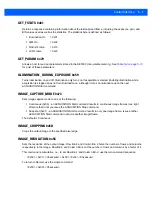
Table 6-1
Frame Time
Parameter
Description
Pixel Clock
Master Clocks
Time
Units
A
Active data time
752
752
28.02
µs
P1
Frame start blanking
71
71
2.66
µs
P2
Frame end blanking
23
23
0.86
µs
Q
Horizontal blanking
94
94
3.52
µs
A + Q
Row time
846
846
31.72
µs
V
Vertical blanking
38,074
38,074
1.43
ms
Nrows
Frame valid time
406,080
406,080
15.23
ms
F
Total frame time
444,154
444,154
16.66
ms
Summary of Contents for SE3300
Page 1: ...SE3300 INTEGRATION GUIDE ...
Page 2: ......
Page 3: ...SE3300 INTEGRATION GUIDE 72E 148589 01 Revision 8 September 2011 ...
Page 6: ...iv SE3300 Integration Guide ...
Page 10: ...viii SE3300 Integration Guide ...
Page 14: ...xii SE3300 Integration Guide ...
Page 18: ...1 4 SE3300 Integration Guide ...
Page 38: ...3 10 SE3300 Integration Guide ...
Page 44: ...4 6 SE3300 Integration Guide Figure 4 5 SE3300 to PL33XX Decoder 21 Pin Flex ...
Page 58: ...5 14 SE3300 Integration Guide ...
Page 68: ...6 10 SE3300 Integration Guide ...
Page 70: ...A 2 SE3300 Integration Guide ...
Page 72: ......
Page 73: ......


