background image

4-4

Computer Group Literature Center Web Site

12-Slot VMEbus Backplane

4

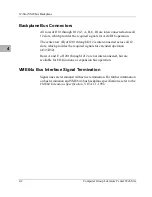
Figure 4-1.  12-Slot Backplane Connectors and Headers

Rear View

+ V2

PB3

11864.00 9709

- V2

+ V1

+3. 3V

+3. 3V

+3. 3V

+3. 3V

- V1

J112

J107

J111

J110

J109

J108

J106

J104

J103

J102

J101

J105

J1

J2

SL

O

T

 1

2

SL

O

T

 1

1

SL

O

T

 1

0

SL

O

T

 9

SL

O

T

 8

SL

O

T

 7

SL

O

T

 6

SL

O

T

 5

SL

O

T

 4

SL

O

T

 3

J1

4

J1

3

J1

2

J1

1

J1

0

J9

J8

J7

J6

J5

J4

+5

V

PB

9

-1

2

V

PB

1

0

+1

2V

PB

1

1

+5

V

PB

1

2

+5

V

PB

1

3

+5

V

PB

1

4

+5

V

PB

1

5

+5

V

PB

1

6

+5

V

PB

1

7

J212

J207

J211

J210

J209

J208

J206

J204

J203

J202 J201

J205

VR1

VR2

+3. 3V

PB27

+3. 3V

PB28

GND

PB29

GND

PB30

GND

PB31

GND

PB32

+5V

PB33

+5V

PB34

+5V

PB35

GND

PB1

8

GND

PB1

9

GND

PB2

0

GND

PB2

1

GND

PB2

2

GND

PB2

3

GND

PB2

4

GND

PB2

5

GND

PB2

6

PB1

PB2

PB4

PB5

PB6

PB7

PB8

SL

O

T

 2

+5V

GROUND

Row 1

Row 4

Row 3

Row 2

J3

Summary of Contents for MVME956AC

Page 1: ...MVME956AC VME Chassis User s Manual MVME956ACA UM2 ...

Page 2: ...rior written permission of Motorola Inc It is possible that this publication may contain reference to or information about Motorola products machines and programs programming or services that are not announced in your country Such references or information must not be construed to mean that Motorola intends to announce such Motorola products programming or services in your country Restricted Right...

Page 3: ... who wants to design OEM systems supply additional capability to an existing system or use the equipment in a lab environment for experimental purposes A basic knowledge of computers and digital logic is assumed Technical knowledge of energy and voltage hazards present in line connected electronic equipment is assumed To use this manual you may need to be familiar with the publications listed in t...

Page 4: ...d trademarks of Motorola Inc All other products mentioned in this document are trademarks or registered trademarks of their respective holders Copyright Motorola Inc 1997 1998 All Rights Reserved Printed in the United States of America October 1998 ...

Page 5: ...s Only Factory Authorized Service Personnel or other qualified maintenance personnel may remove equipment covers for internal subassembly or component replacement or any internal adjustment Do not replace components with power cable connected Under certain conditions dangerous voltages may exist even with the power cable removed To avoid injuries always disconnect power and discharge circuits befo...

Page 6: ... operation In addition Class B equipment will also have an FCC ID number displayed such as FCC ID LNT6ØØADT To determine the classification of your equipment examine the FCC labels which are readily visible on the exterior of the cabinets usually on the back or bottom If all labels have Class B ratings the system is Class B Any Class A label makes the system Class A For FCC Class A NOTE This equip...

Page 7: ... la classe respecte toutes les exigences du Règlement sur le matériel brouilleur du Canada CE Notice European Community Marking a system with the symbol indicates compliance of that Motorola system to the EMC and Low Voltage directives of the European Community A system with the CE marking meets or exceeds the following technical standards EN 55022 Limits and methods of measurement of radio interf...

Page 8: ...ation of Conformity has been made and is on file at Motorola Inc Computer Group 27 Market Street Maidenhead United Kingdom SL6 8AE In addition to the above standards this system has also met the requirements of the following European standards EN 60555 2 Disturbances in supply systems caused by household appliances and similar electrical equipment Part 2 Harmonics EN 60555 3 Disturbances in supply...

Page 9: ...al Precautions 1 7 Operating Environment 1 7 Chassis Cooling Considerations 1 8 Hardware Preparation 1 9 Related Documentation 1 10 CHAPTER 2 Chassis Mount Options Overview 2 1 Chassis Installation Instructions 2 1 Benchtop Operation 2 1 Install the Desktop Cover Kit 2 2 Rack Mounting Option 2 4 CHAPTER 3 Operating Procedures Overview 3 1 Controls and Indicators 3 1 Power Control Procedure 3 2 CHA...

Page 10: ...nd Replacement Procedures Overview 5 1 Following ESD and Safety Procedures 5 1 Power Supply 5 2 Removal 5 2 Replacement 5 4 Disk and Tape Drive 5 6 Removal 5 6 Replacement 5 7 VME64x Bus Backplane 5 9 Removal 5 9 Replacement 5 11 Cooling Fan 5 12 Removal 5 12 Optional Air Filter Kit 5 14 Replacement 5 14 CHAPTER 6 Support Information Introduction 6 1 Drawings Wiring Diagram 6 1 Parts Lists 6 2 ...

Page 11: ... Jumper Wiring 4 8 Figure 5 1 Power Supply Removal Replacement 5 4 Figure 5 2 Disk Tape Drive Removal 5 7 Figure 5 3 Backplane Mounting Card File Removed 5 10 Figure 5 4 Cooling Fan Removal Replacement 5 13 Figure 6 1 MVME956AC Chassis Assembly 1 of 2 6 5 Figure 6 2 MVME956AC Chassis Assembly 2 of 2 6 6 Figure 6 3 MVME956AC Wiring Diagram 6 7 ...

Page 12: ... 4 Table 1 2 12 Slot VME Bus Backplane Specifications 1 5 Table 1 3 Hardware Preparation Items 1 9 Table 4 1 Power Monitor Connection 4 6 Table 4 2 Live Insertion Connections 4 7 Table 6 1 MVME956AC Chassis Parts List 6 2 Table 6 2 MVME956AC AC Major Assemblies 6 4 ...

Page 13: ...sis include VME board injector features in front card cage Board slot keying Internationally approved 550 watt power factor corrected wide ranging power supply 12 slot 64 bit VME64X compatible backplane with 5Vdc 12Vdc and 12Vdc power supplied Optional SCSI drive kits Electrostatic Discharge ESD hardening and Electromagnetic Interference EMI shielding Forced air cooling for power supply mass stora...

Page 14: ... power is not supplied General Description The MVME956AC chassis is designed for OEMs and other technical professionals who wish to integrate individual VME module board level products into a complete compact self contained microcomputer system including disk and or tape drive units This packaging design helps to best meet your specific performance and installation requirements Various options to ...

Page 15: ...the chassis is an ON OFF power switch When the switch is in the OFF position power to the modules is removed but the primary side of the power supply remains energized Power is supplied by an internal 550 watt wide ranging power supply which is mounted vertically toward the rear of the chassis There is provision for 17 rear panel mounted 80 mm interface modules Three DC powered fans provide forced...

Page 16: ...runs constantly when the power supply is plugged in Table 1 1 MVME956AC Chassis Specifications Characteristics Specifications Dimensions Width with front flange 19 00 inches 482 6 mm without front flange 17 20 inches 436 8 mm Depth 19 02 inches 483 1 mm Height 12 22 inches 310 4 mm Weight 32 pounds 15 kg Input voltage 90 132 180 264 Vac Input frequency 47 to 63 Hz Input power 90 132 Vac or 180 264...

Page 17: ...olt current remember to include the backplane termination resistors The system integrator must ensure that the installed peripheral devices and VME module set do not exceed the power supply rating VME Bus Backplane Description and Specifications The MVME956AC chassis contains one 12 slot full 64 bit VME bus backplane mounted to the left of the peripheral device area The backplane can accommodate u...

Page 18: ... integrates a payload into the MVME956AC enclosure it is often necessary to make changes to the payload in order for the system to pass RFI standards The following is a list of conditions that in general must be met in order to achieve compliance with RFI standards At a minimum the chassis must be connected to earth ground through the safety ground wire in the power cord to meet safety and other r...

Page 19: ... compliance if the customer makes changes or additions to the as shipped configuration General Precautions Ensure that the air space above and below the chassis is not blocked and that the inlet screens and optional air filter are clean The air inlet temperature must not exceed 40 degrees Celsius If the MVME956AC is installed in a rack with other chassis be sure that each chassis in the rack is pr...

Page 20: ...are properly cooled The following information will help you to determine whether the cooling is adequate The MVME956AC chassis is designed for an input air temperature below 40 degrees Celsius Three DC powered fans provide forced air cooling for the power supply mass storage enclosure and VME modules The direction of air flow is in at the bottom of the chassis past the power supply and VME modules...

Page 21: ...n Items Item Location of Instructions VME bus backplane jumpers Chapter 4 of this manual Install modules User s manual s for the respective module s Install cables as required MVME956AC installation instructions also other user s manual s as applicable Chassis rack mounting Chapter 2 of this manual Jumper options on modules used in this chassis as required User s manual s for the respective module...

Page 22: ...7 USA http standards ieee org VME64 Extensions Specification VITA 1 1 199X VMEbus International Trade Association http www vita com Vita 1 x Live Insertion for VME64x Requirements Standard VMEbus International Trade Association http www vita com Document Title Motorola Publication Number MVME946 Desktop Cover Kit Installation Instructions MVME946CVR MVME946 Rack Mount Kit Installation Instructions...

Page 23: ...ardware items such as modules and cables while power is applied may damage the equipment Chassis Installation Instructions The MVME956AC chassis can be configured for either rack mounting or for lab benchtop use This section describes the steps necessary to install the optional desktop cover on the chassis for lab benchtop use or to rackmount your unit Benchtop Operation The MVME956AC chassis can ...

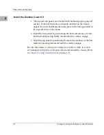
Page 24: ...ovided in the top and sides of the chassis 2 Install the side panels by positioning the ball stud catches over the ball studs and pressing firmly inward until the catches engage 3 Install the top panel by positioning the ball stud catches over the ball studs and pressing downward until the catches engage Be sure the chassis is resting on a strong level table or desk in a clean environment with ple...

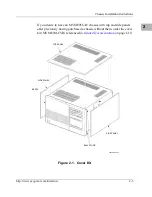
Page 25: ...desire to have an MVME956AC chassis with top and side panels after previously having purchased a chassis without them order the cover kit MVME946CVR referenced in Related Documentation on page 1 10 Figure 2 1 Cover Kit 11819 00 9797 SIDE PANEL BALL STUDS SIDE PANEL BEZEL TOP PANEL ...

Page 26: ...the optional slide mounting kit MVME946RKMT Be sure to observe and follow the special cooling requirements explained in Chapter 1 To rack mount an MVME956AC chassis follow the procedure below 1 Install the two chassis slide sections as shown in using the binder head screws that came in the kit The right and left sections are identical 2 Determine where you will mount the chassis in the rack and ho...

Page 27: ...einstall the front bezel by aligning the pop on off catches on the back of the bezel with the ball studs on the front panel of the chassis Press firmly into place 7 Reconnect the power cable and power on the system Caution Implementation of this procedure may invalidate product safety e g UL CSA etc and RFI regulatory compliance FCC VDE ...

Page 28: ...powered by the 5 Vdc output from the power supply Some of the individual modules used in the chassis may also contain controls and or indicators This manual describes only those that are part of the chassis For a description of other related controls and indicators refer to the documentation that came with your module s The control provided for the MVME956AC chassis is an AC power ON OFF switch Wi...

Page 29: ...wer switch at the front of the chassis to ON The power supply cycles up and the cooling fans immediately come on 4 Power up any peripheral equipment interfaced to the chassis that has its own power on off switch A suggested power off sequence for the chassis is as follows Note Ensure that proper software shutdown procedures have been executed before you continue 1 Power down any peripheral equipme...

Page 30: ...gh user VME modules containing both P1 and P2 connectors The backplane is fully assembled with connectors and terminators It contains 12 connectors on the top row to receive connector P1 of the VME modules 12 connectors on the bottom row to receive VME module expansion connector P2 Backplane Power VME modules that plug into the backplane require voltages of 5 Vdc 12 Vdc and 12 Vdc for operation Th...

Page 31: ...ugh J212 is interconnected across all 12 slots which provides the required signals for extended operation A32 D32 Rows A and C of J201 through J212 are not interconnected but are available for I O functions or expansion bus operation VME64x Bus Interface Signal Termination Signal lines are terminated with active termination For further information on bus termination and VME64x bus backplane specif...

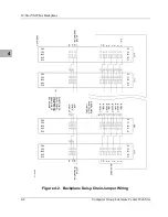
Page 32: ...or networks No special preparation or preassembly is required prior to use You must configure the VME64X bus daisy chain jumpers on the rear wire side of the backplane Refer to VITA 1 x Live Insertion for VME64x requirements standard for more electrical detail and information on daisy chain jumpering Note Backplane daisy chain jumpers normally are shipped with the chassis If necessary additional j...

Page 33: ...SLOT 10 SLOT 9 SLOT 8 SLOT 7 SLOT 6 SLOT 5 SLOT 4 SLOT 3 J14 J13 J12 J11 J10 J9 J8 J7 J6 J5 J4 5V PB9 12V PB10 12V PB11 5V PB12 5V PB13 5V PB14 5V PB15 5V PB16 5V PB17 J212 J207 J211 J210 J209 J208 J206 J204 J203 J202 J201 J205 VR1 VR2 3 3V PB27 3 3V PB28 GND PB29 GND PB30 GND PB31 GND PB32 5V PB33 5V PB34 5V PB35 GND PB18 GND PB19 GND PB20 GND PB21 GND PB22 GND PB23 GND PB24 GND PB25 GND PB26 PB1...

Page 34: ...owing procedure is suggested for installing the jumpers 1 Attach an ESD strap to your wrist Attach the other end of the ESD strap to the chassis as a ground The ESD strap must be secured to your wrist and to ground throughout the procedure 2 Perform an operating system shutdown Turn the AC or DC power off and remove the AC cord or DC power lines from the system 3 At the rear of the backplane selec...

Page 35: ...on all pairs of pins for each backplane slot that will not be occupied by a VME64x module Pin Assignments Power Monitor Connection Connectors J1 and J3 provide for the power monitor signals ACFAIL SYSFAIL and SYSRESET They have the following pinouts For the location of these connectors see Figure 4 1 on page 4 4 Table 4 1 Power Monitor Connection Pin Assignment for J1 Connector Pin Assignment for ...

Page 36: ...r IACK signal jumpers can be used with a user supplied daisy chain switch module This switch module incorporates the backplane daisy chain bypass circuits Header J2 can be used to monitor IACK signal on both pin 1 and pin 2 For further information refer to the VITA 1 x Live Insertion for VME64x requirements standard Table 4 2 Live Insertion Connections Sockets J4 through J14 Pin 1 5V Pin 2 LI O Pi...

Page 37: ...RECTION OF DAISY CHAIN PROPAGATION VIEWED FROM REAR SIDE OF BACKPLANE BG0IN BG0OUT BG1IN BG1OUT BG2IN BG2OUT BG3IN BG3OUT REMOVABLE SHUNT PLUG JUMPER J102 J101 J112 J111 PIN CARD SLOT BUS GRANT ACTIVE TERMINATION 2114 9710 D32 Z32 ACTIVE TERMINATION IACK IACKIN IACKOUT C32 B32 A32 D32 Z32 C32 B32 A32 D32 Z32 C32 B32 A32 D32 Z32 C1 B1 A1 D1 Z1 C1 B1 A1 D1 Z1 C1 B1 A1 D1 Z1 C1 B1 A1 D1 Z1 ...

Page 38: ...ety Procedures Motorola strongly recommends that you use an antistatic wrist strap and a conductive foam pad when installing or upgrading the system Electronic components such as disk drives computer boards and memory modules can be extremely sensitive to ESD After removing the component from the system or its protective wrapper place the component flat on a grounded static free surface and in the...

Page 39: ...D strap to your wrist Attach the other end of the ESD strap to the chassis as a ground The ESD strap must be secured to your wrist and to ground throughout the procedure 2 Perform an operating system shutdown Turn the AC or DC power off and remove the AC cord or DC power lines from the system Power Supply The suggested procedure for the removal and replacement of the power supply assembly is as fo...

Page 40: ...om the right side of the chassis Remove the additional screws from the back of the chassis 5 Disconnect the cable assemblies from the power supply or from the backplane if access to the power supply connections is difficult 6 Disconnect the 5V 12V 12V and RTN wires from the connections on the power supply 7 Slide the power supply assembly vertically up and out of the chassis ...

Page 41: ... Figure 5 1 Power Supply Removal Replacement Replacement To replace the power supply assembly or to install an exchanged assembly follow these procedures 1 Slide the power supply assembly vertically back into the chassis 2 Reconnect the 5V 12V 12V and RTN wires disconnected in Step 6 ...

Page 42: ...4 Reinstall the power supply mounting screw from the side of the chassis Reinstall the screws you removed from the back of the chassis in Step 4 above 5 Replace the chassis top cover with the screws removed in Step 3 above 6 Slide the MVME956AC chassis back into its rack mounting or reinstall the top and side panel on your lab benchtop unit ...

Page 43: ...l the drive out of the chassis Disconnect the data and power cables Remove the drive from the chassis 6 Remove the screws connecting the drive mount bracket to the drive Note If this is a permanent removal ensure that the remaining drive identifications are correct and the terminating resistor is properly installed 7 If the drive is to be immediately replaced go on to the replacement procedure at ...

Page 44: ...ts to the drive The longer screws may damage the drives Ensure that all drives are properly identified and that the terminating resistor is installed or removed as applicable 2 Reconnect the power and data cables 3 Position the side access cover on the screws to engage the keyhole slots properly The washers must be on the outside of the cover 4 When the screws have properly engaged the keyhole slo...

Page 45: ...ment Procedures 5 5 Replace the front bezel 6 Slide the MVME956AC chassis back into its rack mounting or replace the side panel and the top panel to your lab benchtop unit To reset the jumper addresses refer to the installation instructions that came with your drive ...

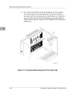
Page 46: ...he rear card file subassembly from the rear of the chassis by removing the screws on the left and right sides of the card file 6 Remove all internal cables connected at the rear of the backplane 7 Remove all power wires from the rear of the backplane Note Mark the wire locations carefully so they can be correctly reinstalled Incorrect connection of these wires can cause damage to the equipment 8 D...

Page 47: ...ving the screws from the front of the backplane Note that the adhesive associated with the insulating tape on the stiffener may make the removal of the stiffener from the backplane somewhat difficult Take caution to prevent damage to the backplane when prying the stiffener off Figure 5 3 Backplane Mounting Card File Removed 11869 00 9710 ...

Page 48: ...ed in Step 9 above 5 Attach the ground bus bar to the backplane with the screws removed in Step 8 above 6 Connect all power wires removed in Step 7 above 7 Connect all cables removed in Step 6 above to the rear of the backplane 8 Slide the card file back into position and attach with the screws removed in Step 5 9 Install the modules removed in Step 2 above 10 Replace the top cover of the chassis ...

Page 49: ... and Table 7 2 on page 7 4 for parts identification and location 4 At the left and right side of the chassis remove the three screws along each side of the base which hold the hinged fan tray and air filter door in the chassis 5 If the MVME956AC is not mounted in a rack lay the unit on one side 6 Remove the screws that keep the fan tray and air filter door secured 7 Swing the fan tray and air filt...

Page 50: ...Cooling Fan http www mcg mot com literature 5 13 5 Figure 5 4 Cooling Fan Removal Replacement ...

Page 51: ... the new fan to the fan tray with the screws removed in Step 9 above 2 Plug the appropriate fan wire connector into its mating connector 3 Rotate the fan tray and air filter door back into place and secure them with the screws removed in Step 4 and Step 6 of the removal procedure Set the unit upright if it is not mounted in a rack 4 Reinstall the front bezel 5 Slide the MVME956AC chassis back into...

Page 52: ...eets Drawings Wiring Diagram Chassis assembly drawings for the MVME956AC chassis are provided in this chapter A chassis wiring diagram is included as part of the main assembly drawing of the chassis These drawings represent the latest design at the time of printing Occasionally minor component changes are made at the factory Therefore when replacing defective components or parts always use the sam...

Page 53: ...B02x Bezel assembly 956 01 W2030E01x AC power supply 01 W2287D01x Assy fan 24V Cholla 01NW9804E44 Backplane assy 1 2 slot VME ext 07 W5215C01x Access cover left side 07 W5224C01x Access cover right side 07 W5225C01x Card cage 07 W5329C01x Cover 956 07 W6858B01x SCSI cable cover 07 W5331C01x Stiffener 956 motherboard 07 W6907B01x Fan guard Cholla 07NW9502A96 Guard 20x20mm SW 30 W2285D02x Power cabl...

Page 54: ... Terminator 187 X 02 quick connect 29NW9805B38 Lug quick connect 187 w blde 04NW9005A60 Flat washer FLT 10 03NW9004B48 Captive Screw m2 5 03SW990F608 Sem Phillips 03SW990F012 Sem Phillips panhead 10 32X3 4 03SW990F604 Sem Phillips panhead 6 32X1 4 03SW990F606 Sem Phillips panhead 6 32X3 8 03SW990F626 Sem Phillips 6 32X1 5 8 03SW990F806 Sem Phillips panhead 8 32X3 8 03SW991F604 Screw Phillips flath...

Page 55: ...E956 AC Chassis assy Chassis with card cage power supply backplane power switch and cooling fans Operates on 115 220 Vac input power 01 W2030E01X Power supply Power supply 550W 115 230 Vac input 5 Vdc 12 Vdc and 12 Vdc Includes cooling fan and housing with cables 01 NW9804E44 Backplane VMEmodule backplane Contains 12 connectors for P1 and P2 of VME bus ...

Page 56: ...877 00 9710 Foot Card Cage Access Cover Top Cover Voltage Warning PWB Assy Cable Assy DC SCSI Cable Cover Front Panel Power Supply BDL 1 wide Left Side Cable Assy Switch Enable Bezel Assembly Fan Assembly Chassis Access Cover Right Side harness enable 12 slot blank Assembly Label Assembly Stiffener ...

Page 57: ...ature Center Web Site Support Information 6 Figure 6 2 MVME956AC Chassis Assembly 2 of 2 11876 00 9710 Filter Door Fan Filter Frame Fan Assembly AIR FLOW Fan Guard Optional Air Filter Chassis Top Cover Access Cover Right Side ...

Page 58: ...AN FAN P11 P11 P11 PB TO DRIVES J14 FRONT PNL SWITCH FAN NC WHT BLK WHT RED WHT BLK J1 RED WHT BLK WHT SIG RTN INHB PWR GD LED DRV RET 12V 12V VIO F4 BLK F6 ORG F5 8 PB 7 PB 6 PB 5 PB 4 PB 3 PB 2 PB 1 5V GND GND 12V 12V PB 35 PB 34 PB 33 PB 32 PB 31 PB 30 PB 29 PB 28 PB 27 PB 11 PB 19 PB 18 GND PB 11 PB 10 PB 9 J11 A J11 B J11 C ORG 12V BLK GND RED 5V BLK GND 5V Row 1 Row 2 Row 3 Row 4 GND ORN VIO...

Page 59: ...ing 1 8 documentation 1 10 features 1 1 installing 2 1 major assemblies 1 2 operating environment 1 8 power supply 1 3 regulatories 1 6 setup precautions 1 7 specifications 1 3 use and purpose 1 2 chassis assemblies removal and replacement 5 1 control switch location 3 1 cooling requirements 1 8 cover kit installation 2 2 cover kit removal 2 4 D d SYSRES 4 6 daisy chain configure jumpers 4 3 insta...

Page 60: ...nchtop operation 2 1 install jumpers 4 5 power control 3 2 power off 3 2 power on 3 1 safety 5 1 to rack mount 2 4 publications related 1 10 R rack mount slide mounting kit 2 4 remove replace AC power supply 5 2 to 5 5 remove replace backplane 5 9 to 5 11 remove replace cooling fan 5 12 to 5 14 remove replace drives 5 6 to 5 8 RF emissions precautions 1 7 RFI compliance 1 7 1 8 RFI standard 1 6 S ...

Reviews: