General Description
http://www.mcg.mot.com/literature
1-3
1
❏
VME module backplane. Contains 12 connectors for P1 and P2 of
VME bus.
The basic chassis, power supply, and backplane are described in this
manual. The optional disk drives, tape drives, and controllers are described
in their respective manuals or reference sheets. Refer to the
Related
Documentation
on page 1-10 for additional information.
Chassis Description and Specifications
The MVME956AC chassis is designed for industry-standard 3-row VME
modules and VME64X modules not req3.3Vdc backplane power.
The chassis accommodates five additional peripheral drive and houses a
VME module card cage with 12 VME bus slots. The front panel opening
accommodates the five 5-1/4-inch, half-height SCSI peripheral devices.
The control for the chassis is an ON/OFF power switch.When the switch
is in the OFF position, power to the modules is removed but the primary
side of the power supply remains energized. Power is supplied by an
internal 550 watt wide-ranging power supply, which is mounted vertically
toward the rear of the chassis. There is provision for 17 rear panel-mounted
80 mm interface modules.
Three DC-powered fans provide forced air cooling for the power supply,
mass storage enclosure, and VME modules. Convection cooling is used for
the rear-mounted modules.
The rear of the chassis supports standard double-high Eurocard panels and
80 mm modules such as MVME7XX series modules.
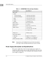
Table 1-1
lists the
specifications for the MVME956AC chassis and power supply. Table 1-3
lists the specifications for the 12-slot backplane. Specifications for the
SCSI drives and VME modules used in the MVME956AC chassis are
given in their respective manuals or reference sheets. Refer to
Related
Documentation
on page 1-10 for information.


