background image

MOTOMESH 1.2 Wireless Modem Card Users Guide 

6881011Y52-D   January 2007 

2-5 

13 


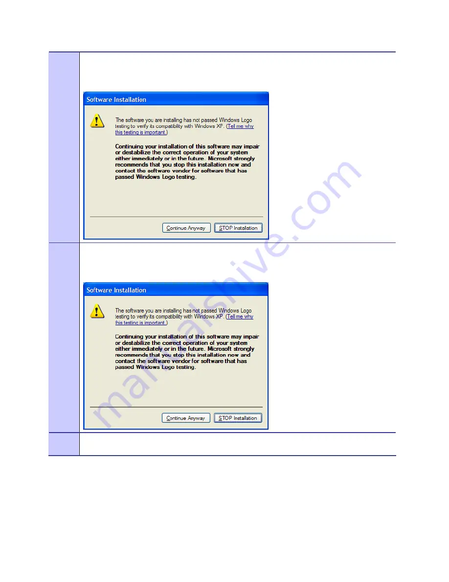
Software Installation

 dialog indicates that the software is not Windows Logo tested, select the 

Continue Anyway

 button to complete the installation process.  

Figure 2-7 

Software Installation Dialog Box 


14 


If a second 

Software Installation

 dialog box is displayed as shown in 

Figure 2-8

.  Click on the 

Continue 

Anyway

 button to complete the installation process. 

Figure 2-8 

Software Installation Dialog Box 


15 


Select the 

Continue Anyway

 button if additional windows display on the screen containing the same 

screen contents as in the step above. 

Summary of Contents for MOTOMESH 1.2

Page 1: ...MOTOMESH 1 2 Wireless Modem Card Users Guide January 2007 6881011Y52 D ...

Page 2: ...MOTOMESH 1 2 Wireless Modem Card Users Guide 6881011Y52 D January 2007 ii This page intentionally left blank ...

Page 3: ...pt for the normal nonexclusive royalty free license to use that arises by operation of law in the sale of a product Disclaimer Please note that certain features facilities and capabilities described in this document may not be applicable to or licensed for use on a particular system or may be dependent upon the characteristics of a particular mobile subscriber unit or configuration of certain para...

Page 4: ...MOTOMESH 1 2 Wireless Modem Card Users Guide 6881011Y52 D January 2007 iv This page intentionally left blank ...

Page 5: ...rking with the Antenna 3 1 Connecting the Antenna Assembly 3 1 Disconnecting a Pigtail Antenna Assembly 3 2 Connecting the Magnetic Antenna Assembly Optional 3 3 Installing the WMC6300 and the WMC7300 3 5 Installing the Wireless Modem Card 3 5 Removing the Wireless Modem Card 3 11 Chapter 4 MeshTray 4 1 MeshTray System Tray Icon Status 4 1 Starting MeshTray 4 2 MeshTray Tab Contents 4 3 Status Tab...

Page 6: ...ustomer Information 5 1 Customer Service Information 5 1 Obtaining Support 5 1 System Information 5 1 Return Material Request 5 2 Radio Products and Services Division 5 2 Radio Products and Services Division Telephone Numbers 5 2 Returning System Components to Motorola 5 2 Returning FREs 5 2 Chapter 6 Certification and Safety Information 6 1 FCC Regulatory Information 6 1 FCC Information 6 1 FCC R...

Page 7: ...ng Previous Software From Your Computer W2K 2 9 Figure 2 17 Confirm File Deletion W2K 2 10 Figure 2 18 Uninstalling Software Deleting Files W2K 2 10 Figure 2 19 Installing Files Window W2K 2 11 Figure 2 20 Performing Setup Actions W2K 2 11 Figure 2 21 MOTOMESH Setup Select Options Dialog Box 2 12 Figure 2 22 MOTOMESH Installed Successfully W2K 2 13 Figure 3 1 Attach the Antenna to the WMC6300 or t...

Page 8: ... Protection Panel 4 6 Figure 4 4 MeshTray and Windows TCPIP DHCP and DNS Setting Options 4 8 Figure 4 5 Control Panel Network and Internet Connections Icon 4 9 Figure 4 6 Network and Dial up Connections Window 4 9 Figure 4 7 Local Area Connection Properties Dialog Box 4 9 Figure 4 8 Local Area Connection Properties Dialog Box 4 11 Figure 4 9 MeshTray Geo Position Tab 4 12 Figure 4 10 MeshTray Rout...

Page 9: ...ables Table 4 1 MeshTray Icon States 4 1 Table 4 2 Status Tab Adapter Information Section 4 3 Table 4 3 Geographic Reporting section 4 5 Table 4 4 Routing Tab Icons 4 13 Table 4 5 Authentication Control Icons 4 15 Table 4 6 IAP Authentication Dialog 4 16 ...

Page 10: ...List of Tables 6881011Y52 D January 2007 x This page intentionally left blank ...

Page 11: ...ing the Antenna Assembly 3 1 Procedure 3 2 Disconnecting the Antenna Assembly 3 2 Procedure 3 3 Installing the Magnetic Mount Antenna Assembly 3 3 Procedure 3 4 Installing the Wireless Modem Card 3 5 Procedure 3 5 Removing the Wireless Modem Card 3 11 Procedure 4 1 Starting MeshTray 4 2 Procedure 4 2 Changing the Control Channel 4 6 Procedure 4 3 Setting a User Supplied Address 4 9 Procedure 4 4 C...

Page 12: ...List of Procedures 6881011Y52 D January 2007 xii This page intentionally left blank ...

Page 13: ...ith the Wireless Modem Card is also included General System Requirements Host computers must comply with the following minimum requirements to ensure optimal performance of the WMC6300 and the WMC7300 Windows XP Minimum System Requirements Laptop or Notebook PC running the Microsoft Windows XP Service Pack 1 operating system 500 MHz Processor 10 MB of available hard disk storage Keyboard Mouse CD ...

Page 14: ... ROM The CD ROM contains a PDF version of the Wireless Modem Card User s Guide The CD also contains an installation executable to load Adobe Acrobat Reader software if it is not already resident on your computer External Connections and LED Indicators The WMC6300 and the WMC7300 Wireless Modem Card is designed for insertion into an industry standard Type II PCMCIA card slot located in a Host devic...

Page 15: ... If you are running Windows XP Service Pack 2 SP2 Windows Firewall is turned on by default It is recommended that you disable the firewall when using your Wireless Modem Card Procedure 2 1 MOTOMESH Client Software Installation on Windows XP 1 Close and exit any existing MOTOMESH applications running on the computer prior to installation 2 Insert the Software and Documentation CD into the CD ROM dr...

Page 16: ...ntinue the installation process It is recommended that the Automatically Launch MeshTray at Startup checkbox is selected allowing MeshTray to be available each time the computer is restarted and whenever a Wireless Modem Card WMC is inserted Figure 2 2 MOTOMESH Setup Startup Options XP 8 The Ready to Install dialog displays the Install Folder location and the Shortcut Folder name that will be used...

Page 17: ... been previously installed on your computer the Information dialog box will be displayed as shown in Figure 2 4 Select the Uninstall button to remove the existing MOTOMESH drivers and continue the installation process If you choose not to continue click the Cancel button Figure 2 4 MOTOMESH Setup Previously Installed Software Detected XP ...

Page 18: ...install operation When the operation has completed click on the Close button to dismiss the dialog Figure 2 5 MOTOMESH Setup Uninstalling Software XP 11 The Installing Files window will be automatically dismissed as soon as file installation has completed Figure 2 6 MOTOMESH Setup Installing Files Window XP 12 The Performing Setup Actions dialog displays a status bar to indicate the progress of th...

Page 19: ...e the installation process Figure 2 7 Software Installation Dialog Box 14 If a second Software Installation dialog box is displayed as shown in Figure 2 8 Click on the Continue Anyway button to complete the installation process Figure 2 8 Software Installation Dialog Box 15 Select the Continue Anyway button if additional windows display on the screen containing the same screen contents as in the s...

Page 20: ...e Installation Dialog Box Select Options 17 If selected the ReadMe file will be displayed Review the contents of the file and then dismiss the dialog box by clicking on the X located in the upper right corner of the dialog You MUST close the ReadMe file to complete the installation 18 From the MOTOMESH Installed Successfully dialog click on the Finish button to exit Be sure to close the ReadMe fil...

Page 21: ...MESH Client Software Installation on Windows 2000 1 Close and exit any existing MOTOMESH applications running on the computer prior to installation 2 Insert the MOTOMESH Software and Documentation CD into the CD ROM drive The installation should begin automatically 3 If the installation program does not start automatically select Start Run then type d setupmotomeshclient exe where d specifies the ...

Page 22: ...available each time the computer is restarted Figure 2 12 MOTOMESH Setup Startup Options Dialog Box W2K 6 The Ready to Install dialog box will be displayed as shown in Figure 2 13 This dialog box displays the Install Folder location and the Shortcut Folder name that will be used to install the MOTOMESH software Click on Next to proceed with the installation process Figure 2 13 MOTOMESH Setup Ready...

Page 23: ...etup Software Previously Installed W2K 8 From the Confirm Action dialog select the Yes button to remove all of the previously installed components If you do not want to continue click on the No button Figure 2 15 Confirm Action Remove Existing Components 9 The Uninstalling Software dialog will display the un installation status Figure 2 16 Removing Previous Software From Your Computer W2K ...

Page 24: ...the Confirm File Delete dialog displays on the screen select the Yes to All button Figure 2 17 Confirm File Deletion W2K 11 The Uninstalling Software dialog will display the deleting file status select Close when done Figure 2 18 Uninstalling Software Deleting Files W2K ...

Page 25: ...es window will be dismissed as soon as the installation of the files is complete Figure 2 19 Installing Files Window W2K 13 During the Setup process the Performing Setup Actions dialog box displays a status bar that indicates the progress of the installation Figure 2 20 Performing Setup Actions W2K ...

Page 26: ...eadMe file during the installation and to run MeshTray immediately following installation Click on the Next button to proceed with the installation process Figure 2 21 MOTOMESH Setup Select Options Dialog Box 15 If selected the ReadMe file will be displayed Review the contents of the file and then dismiss the dialog box by clicking on the X located in the upper right corner of the dialog box ...

Page 27: ...ss Modem Card Users Guide 6881011Y52 D January 2007 2 13 16 The MOTOMESH Installed Successfully dialog will appear as shown in Figure 2 22 Click on the Finish button to exit Figure 2 22 MOTOMESH Installed Successfully W2K ...

Page 28: ...Chapter 2 Software Installation 6881011Y52 D January 2007 2 14 This page intentionally left blank ...

Page 29: ...must be completed before following the procedures outlined in this chapter Working with the Antenna The following sections will focus on the proper handling and usage of antennas when using a wireless modem card Connecting the Antenna Assembly Complete the following procedure to connect the Antenna Assembly Knuckle or Pigtail type to the Wireless Modem Card for use in a standard laptop computer Al...

Page 30: ...nnas Never use the WMC6300 or the WMC7300 with the Antenna disconnected from the Card Disconnecting a Pigtail Antenna Assembly Complete care should be taken when disconnecting an antenna from the WMC6300 or the WMC7300 card Follow the procedure below for correct antenna disconnection instructions Procedure 3 2 Disconnecting the Antenna Assembly 1 When disconnecting a pigtail antenna from the Wirel...

Page 31: ...ct the MMCX directly to the card Procedure 3 3 Installing the Magnetic Mount Antenna Assembly 1 The graphic below depicts the Magnetic Mount Antenna Cable with antenna Circle C the MMCX adapter and the WMC6300 card Circles A and B designate the required cable connection points Figure 3 2 Magnetic Mount Antenna N Type SMA to MMCX adapter and WMC6300 2 Attach the Magnetic Antenna shown in Circle C F...

Page 32: ...CX adapter cable from detail of Circle A in Figure 3 2 Figure 3 3 Antenna Cable end connecting to MMCX adapter 5 Connect the MMCX adapter cable to the WMC6300 or the WMC7300 by pressing it firmly into the card s antenna port shown in Circle B Figure 3 2 Figure 3 4 N Type SMA to the MMCX adapter connecting to the WMC6300 The connector will snap into place when properly inserted 6 Insert the WMC6300...

Page 33: ...the WMC7300 wireless modem cards The same installation procedure applies to both wireless modem card model numbers Procedure 3 4 Installing the Wireless Modem Card 1 Locate an available Type II PCMCIA card slot in the computer If necessary remove the slot dust cover from the slot 2 To insure the correct orientation insert the Wireless Modem Card into the computer s PCMCIA card slot with the label ...

Page 34: ...ng the clip and vertically oriented when the laptop is in use as shown in Figure 3 6 Figure 3 6 Proper Orientation of Antenna 4 The first time that the card is inserted a message will be displayed indicating that the PC card has been found as shown in Figure 3 7 Figure 3 7 Found New Hardware Popup Dialog box ...

Page 35: ...rify that the Install the software automatically Recommended radio button is selected and then click on the Next button Figure 3 8 Found New Hardware Wizard Serial PC Card 6 The Found New Hardware dialog will display the progress information for establishing the restore point and backing up old files as shown in Figure 3 7 Figure 3 9 Found New Hardware Wizard Loading Files ...

Page 36: ...ion dialog box shown in Figure 3 10 will be displayed Click on the Continue Anyway button in the Hardware Installation dialog box Figure 3 10 Hardware Installation Dialog Box 8 The Found New Hardware Wizard Complete dialog box will appear as shown in Figure 3 11 Click on the Finish button Figure 3 11 Found New Hardware Wizard Complete ...

Page 37: ...layed as shown in Figure 3 12 Verify that the Install the software automatically Recommended radio button is selected and then click on the Next button Figure 3 12 Found New Hardware Wizard 10 A Loading Files dialog box will appear as shown in Figure 3 13 Go on to the next step Figure 3 13 Found New Hardware Wizard Loading Files ...

Page 38: ...stallation dialog box Figure 3 14 click on the Continue Anyway button Figure 3 14 Hardware Installation Dialog Box WMC6300 PC Card 12 The Found New Hardware Wizard Complete dialog box will be displayed as shown in Figure 3 15 Click on the Finish button Figure 3 15 Found New Hardware Wizard Complete ...

Page 39: ... ensure that power to the card is disabled prior to removal Complete the following procedure prior to ejecting the Wireless Modem Card from the computer Procedure 3 5 Removing the Wireless Modem Card 1 Click on the Unplug or Eject Hardware icon in the system task bar Select Safely remove Generic Multifunction PC Card from the popup menu as shown in Figure 3 17 Figure 3 17 Unplug or Eject Hardware ...

Page 40: ...Chapter 3 Wireless Modem Card Installation 6881011Y52 D January 2007 3 12 3 Eject the WMC6300 from the PCMCIA slot as shown in Figure 3 19 Figure 3 19 Removing the WMC6300 from the PCMCIA slot ...

Page 41: ... in peer to peer mode IAP association is not possible intentionally or unintentionally and a wireless mesh network is automatically accessed with the use of any available peer devices instead The table below describes all the possible states that the MeshTray icon will exhibit in the Windows system tray Table 4 1 MeshTray Icon States Icon State Explanation Peer to Peer with Neighbors The icon indi...

Page 42: ...o restore the application to a property sheet tab style interface as shown in Figure 4 1 Excellent IAP Association Infrastructure mode When the WMC is associated with an IAP not peer to peer the MeshTray icon displays the Link Quality to the associated IAP as color coded bars The greater the number of bars the better the Link Quality Very Good IAP Association Same explanation as listed for the Exc...

Page 43: ...Table 4 2 Status Tab Adapter Information Section Status Tab Item Explanation Description Indicates the device type MAC Address Displays the MAC Address assigned to the Wireless Modem Card on the current computer being viewed through MeshTray RF Frequency Displays either 2 4 or 4 9 GHz RF operating frequency Adapter Type Describes the type of adapter Firmware Version Current version of the firmware...

Page 44: ...n Infrastructure mode as opposed to Peer to Peer A device that is running in Peer to Peer mode will display a yellow percentage bar along with the word inactive Operating Mode Graphic Infrastructure The two modes that a MOTOMESH or a MEA wireless device operates in is Infrastructure or Peer to Peer Within the MeshTray Status tab the graphic mode automatically adjusts to the operating mode The Infr...

Page 45: ...wise the Geo Position tab would not be shown For additional information about the Geo Position tab and its use please see the Geo Position tab section of this documentation If the Display Geographic Position checkbox is grayed out and a license has been purchased check with your company s Network Administrator about enabling this option from within the MOTOMESH MeshManager application Geographic R...

Page 46: ...ing the Control Channel 1 Click on the Change Control Channel button located on the Configuration tab if you are required to change the control channel at the request of a Network Administrator A Password window will display Figure 4 3 Password Protection Panel 2 Enter the password provided by your network administrator and then select the OK button Antenna Cable Length numbers can be used in thes...

Page 47: ...l be explored in the following sections please see the figure below for a visual explanation When the Enable Adapter s DHCP Server checkbox is selected an IP address will be provided to Windows by the adapter s internal DHCP server A unique IP address will be created from the device s MAC address and a subnet mask will be available To complete the configuration the default gateway and the DNS sett...

Page 48: ...dress Subnet Mask and Default GW come from MAC Address Hash Yes Has Network Manager configured a static host address on the WMC6300 No IP Address Subnet Mask and Default GW come WMC6300 devman configuration Yes Does a DHCP server exist on the network No IP Address Subnet Mask and Default GW come from DHCP Server Yes Is Windows configured for static DNS config Yes DNS Servers come from DHCP Server ...

Page 49: ... From the Start menu select Settings Control Panel Double click on the Network and Dial up Connections icon Figure 4 5 Control Panel Network and Internet Connections Icon 2 The Network and Internet Connections window will be displayed Double click on Network and Internet Connections then right click on the Local Area Connection icon and select Properties Figure 4 6 Network and Dial up Connections ...

Page 50: ... only necessary when a DHCP server does not exist on the Network Procedure 4 4 Configuring the DNS Address 1 Select Start Control Panel to display the Windows Control Panel 2 On the Control Panel double click on the Network and Internet Connections icon and then double click on the Network Connections icon ...

Page 51: ...igure 4 8 5 Click on the Properties button 6 Click on the Advanced button 7 Click on the DNS tab 8 Click on the DNS Add button 9 Enter the DNS Server IP Address provided by the Network Administrator and then click the Add button 10 Click on the OK button to close the Advanced TCP IP Settings dialog box 11 Click on the OK button to close the Internet Protocol TCP IP Properties dialog box 12 Click o...

Page 52: ... Device and associated Routing and Neighbor table information The Threshold setting can be set to a minimum of 100 dBm Although the first two digits of the QDMA Transceiver MAC address on the label for a Subscriber Device WMC may read 00 due to the operational requirements of a MOTOMESH network the Routing and Neighbor tables in MeshTray will display 02 for the first two digits local bit set for a...

Page 53: ... internally This means that the first hop is from the SD to the IAP while the second hop is inside the IAP itself IAP to internal WR component Neighbor Table The Neighbor Table displays the MAC address and the Signal Level for the adjacent nodes that the WMC may route through depending on the desired end node The Last Rate column displays the last data rate used to transmit user data to the neighb...

Page 54: ...ated to routing data IAP The Globe icon represents an Intelligent Access Point IAP in the MEA network A MEA Intelligent Access Point is an infrastructure device that allows access to the wired network MeshTray Security Tab The Security tab is used to set the IAP and Peer Authentication passwords to gain access to the network Figure 4 11 MeshTray Security Tab Require Authentication to IAP Connectio...

Page 55: ...r Incoming Connections When in peer to peer mode select one of the radio buttons to select the desired authentication option Table 4 5 Authentication Control Icons Icon Description Local Authenticate all wireless access Authentication is based on Peer information See the Peer Authentication section in this chapter Force Authorized Allow any wireless access Allow all clients Force Unauthorized Deny...

Page 56: ... since it will allow anyone who has access to the Windows user account Peer Authentication The Peer Authentication pane displays a table containing the Group Name and Save Pwd stats for all users within a Peer Authorization group as shown in the figure below In a Peer to Peer network the user can specify a group name and password to gain access to all other devices associated as peers The same gro...

Page 57: ...n Activity tab displays Infrastructure IAP Activity and Peer to Peer Group Activity with an associated Time stamp and Count for the number of attempted authentications The icons displayed in the Time column identify whether attempted authentications were successful or if they failed Figure 4 13 MeshTray Authentication Activity Tab ...

Page 58: ...Chapter 4 MeshTray 6881011Y52 D January 2007 4 18 This page intentionally left blank ...

Page 59: ...7144 USA Obtaining Support Motorola provides technical support services for your system and recommends that you coordinate warranty and repair activities through the Motorola System Support Center SSC When you consult the Motorola SSC you increase the likelihood that problems are rectified in a timely fashion and that warranty requirements are satisfied Check your contract for specific warranty an...

Page 60: ...es FREs North America 800 221 7144 Radio Products and Services Division The Radio Products and Services Division is your source for manuals and replacement parts Radio Products and Services Division Telephone Numbers The telephone numbers for ordering are 800 422 4210 US and Canada orders The Fax numbers are 800 622 6210 US and Canada orders The number for help identifying an item or part number i...

Page 61: ... model kit numbers and serial numbers on the job ticket as necessary If the warranty is out of date you must have a purchase order Print the return address clearly in block letters Provide a phone number where your repair technician can be reached Include the contact person s name for return Pack the assembly tightly and securely preferably in its original shipping container ...

Page 62: ...Chapter 5 Customer Information 6881011Y52 D January 2007 5 4 This page intentionally left blank ...

Page 63: ...ese limits are designed to provide reasonable protection against harmful interference in a residential installation This equipment generates uses and can radiate radio frequency energy and if not installed and used in accordance with the instructions may cause harmful interference to radio communications However there is no guarantee that interference will not occur in a particular installation If...

Page 64: ...s manual and the hardware and software guides on the MOTOMESH CD will result in user exposure that is substantially below the FCC recommended limits Do not touch or move the antenna s while the unit is transmitting or receiving Do not hold any component containing a radio such that the antenna is very close to or touching any exposed parts of the body especially the face or eyes while transmitting...

Page 65: ...f this radio according to the instructions found in this manual and the hardware and software guides on the MOTOMESH CD will result in user exposure that is substantially below the FCC recommended limits Do not touch or move the antenna s while the unit is transmitting or receiving Do not hold any component containing a radio such that the antenna is very close to or touching any exposed parts of ...

Page 66: ...Chapter 6 Certification and Safety Information 6881011Y52 D January 2007 6 4 WMC7300 Product Label Example ...

Page 67: ... 4 2 Install Folder 2 2 IP Address of server to report 4 6 L LED Indicators 1 2 Link Quality 4 1 4 2 4 4 M Magnetic Antenna 3 3 Magnetic Mount Antenna 3 3 3 4 MeshTray exe 4 2 Multifunction PC Card 3 11 N Neighbor Table 4 13 Neighbors 4 1 P PCMCIA card slot 3 5 Peer Authentication 4 16 Peer to Peer 4 1 Peer to Peer 4 1 4 4 4 16 4 17 Pigtail type 3 1 R ReadMe 2 6 2 12 Require Authentication to IAP ...

Page 68: ...Index 6881011Y52 D January 2007 Index 2 This page intentionally left blank ...

Page 69: ...chitecture MiSC Mobile Internet Switching Controller MWR Mesh Wireless Router SBC Single Board Computer SD Subscriber Device a general description to a device type that is usually a WMC or a VMM VMM Vehicle Mounted Modem WMC Wireless Modem Card can apply to any model number WR Wireless Router same as MWR ...

Page 70: ...Glossary 6881011Y52 D January 2007 Glossary 2 This page intentionally left blank ...

Reviews: