M68360QUADS-040 Hardware User’s Manual
OPERATING INSTRUCTIONS
18
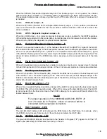
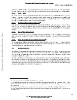
When the TPSQEL (Twisted Pair Signal Quality Error Test Enable) jumper - J4 is in position, the collision
detect circuitry test is enabled, i.e., simulated collision is generated to the EEST collision detect circuitry.
The generated collision does not have any effect over the TP media. When J4 is removed, the above test
is disabled.
3.2.4.5
TPFULDL Jumper - J5
When the TPFULDL (Twisted Pair Full Duplex Mode Select) jumper - J5 is in position, simultaneous
receive and transmit are enabled for the TP port without collision indication. When J5 is removed, the
above is disabled.
3.2.4.6
LOOP - Diagnostic Loopback Jumper - J6
When the LOOP jumper - J6 is removed, diagnostic loop-back mode is enabled for the EEST regardless
of the interface type selected. In this mode, data is transmitted back into the receiver but not to the medium.
When J6 is in position, the diagnostic loop-back mode is disabled.
3.2.5
Hardware Breakpoint Usage Jumper - J7
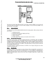
When J7 is connected between pins 1- 2, the hardware BreaKPoinT Out (BKPTO~) signal of the QUICC
is connected to the interrupt logic. When breakpoint is reached, level 7 interrupt is generated to the EC040.
When J7 is connected between pins 2 - 3, BKPTO~ is connected to the Transfer cache Inhibit (TCI~) signal
of the EC040. That way desired memory areas may be “shielded” and prevented from being cached. This
allows for better utilization of the EC040 data cache, keeping one-time accessed data out of the data
cache.
3.2.6
Parity Error Interrupt Jumper - J8
When J8 is positioned in place and parity is enabled, occurrence of parity error, causes a level 5 interrupt
to the EC040 via the QUICC’s interrupt controller. When J8 is removed, parity error interrupts are disabled.
3.2.7
Bus Request Jumper - J9
When J9 is in position, the Bus Request (BR~) Output of the EC040 is connected to the Bus Request Input
of the QUICC. This is the normal operating mode. When J9 is removed, the Bus Request Output of the
EC040 is disconnected from the Bus Request Input of the QUICC, allowing for an external (off-board)
arbiter to be located between them.
3.2.8
Bus Grant Jumper - J10
When J10 is in position the Bus Grant (BG~) Output of the QUICC is connected to the Bus Grant Input of
the EC040. This is the normal operating mode. When J10 is removed, the Bus Grant Output of the QUICC
is disconnected from the Bus Grant Input of the EC040, allowing for an external (off-board) arbiter to be
located between them.
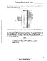
NOTE
For proper operation of the M68360QUADS-040, BOTH J9
and J10 must be In Position, unless an external arbiter is
connected via the expansion connectors.
3.2.9
HALT Indicator - LD10
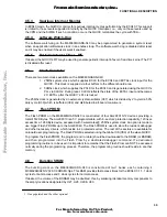
The red LED HALT indicator LD1 is lit whenever the EC040 enters the HALT state. For example, when
the EC040 can not recover from an error, it frees the bus and enters the HALT state.
3.2.10
040RUN Indicator - LD8
The green LED 040RUN indicator is connected to the Transfer In Progress (TIP*) signal. It is lit if the TIP*
signal is low (asserted) and it indicates the activity on the bus.
F
re
e
sc
a
le
S
e
m
ic
o
n
d
u
c
to
r,
I
Freescale Semiconductor, Inc.
For More Information On This Product,
Go to: www.freescale.com
n
c
.
..

