background image

WiMAX CPEo400 Series User Guide

Configuring TCP/IP in Windows 2000

3.

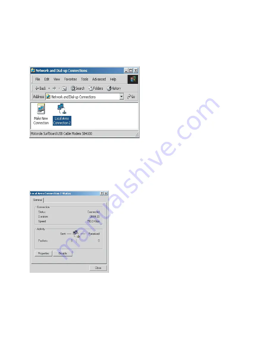
Double-click the

Network and Dial-up Connections

icon to display the Network and

Dial-up Connections window:

Figure 6-2 Network and Dial-up Connections

In the steps that follow, a connection

number

like 1, 2, 3, etc., is a reference that is

displayed on computers with multiple network interfaces. Computers with only one
network interface may only see the label: Local Area Connection.

4.

Click

Local Area Connection

number. The value of number varies from system to system.

The Local Area Connection number Status window is displayed:

Figure 6-3 Local Area Connection

5.

Click

Properties

. Information similar to the following window is displayed:

68P09285A67-D

6-3

MAR 2008

Summary of Contents for CPEo 400 Series

Page 1: ...CPEo 400 Series ...

Page 2: ...se any license under the copyrights patents or patent applications of Motorola or other 3rd Party supplied software except for the normal non exclusive royalty free license to use that arises by operation of law in the sale of a product A list of 3rd Party supplied software copyrights are contained in the Supplemental information section of this document Restrictions Software and documentation are...

Page 3: ...re to Log into the CPE 2 4 Before you Begin Configuration 2 4 Logging into the CPE 2 4 Setup Wizard and Authentication 2 6 Wizard Step One Enable Login Password Protection 2 6 Wizard Step Two Device Time 2 6 Wizard Step Three WiMAX Security 2 6 CPE User Screens 2 8 Chapter 3 Basic Configuration Basic Configuration Overview 3 2 Personalize Menu 3 2 Internet Menu 3 4 Status Menu 3 7 Chapter 4 Advanc...

Page 4: ...iguring TCP IP in Windows XP 6 6 Chapter 7 Important Safety and Legal Information Important Safety Information 7 2 This Product complies with the following RF energy exposure standards and guidelines 7 2 Caring for the Environment 7 7 Disposal of Motorola Equipment in EU Countries 7 7 Disposal of Motorola Networks Equipment in Non EU Countries 7 7 CMM Disclosure 7 7 Copyrights and Trademarks 7 9 N...

Page 5: ...Dial up Connections 6 3 Figure 6 3 Local Area Connection 6 3 Figure 6 4 Properties 6 4 Figure 6 5 Select Network Connection Type 6 4 Figure 6 6 Select Network Protocol 6 5 Figure 6 7 Internet Protocol TCP IP Properties 6 5 Figure 6 8 Windows XP Start Window 6 6 Figure 6 9 Control Panel 6 6 Figure 6 10 Network and Internet Connections 6 7 Figure 6 11 Control Panel Classic View 6 7 Figure 6 12 Netwo...

Page 6: ...List of Figures iv 68P09285A67 D MAR 2008 ...

Page 7: ...MAX Security Fields 3 5 Table 3 6 Firewall Fields 3 6 Table 3 7 Dynamic DNS Fields 3 6 Table 4 1 Port Forwarding Basic Fields 4 3 Table 4 2 Port Forwarding Forwarding Screen Fields 4 3 Table 4 3 DHCP Server Fields 4 4 Table 4 4 Lease Status Fields 4 5 Table 4 5 Lease Reservation Fields 4 5 Table 4 6 Software Tab Fields 4 7 Table 4 7 System Tab Fields 4 7 Table 5 1 Glossary Terms 5 2 Table 7 1 Comp...

Page 8: ...List of Tables vi 68P09285A67 D MAR 2008 ...

Page 9: ...About This Manual WiMAX CPEo400 Series User Guide 68P09285A67 D 1 MAR 2008 ...

Page 10: ... since it was first released Version Information Table 1 Manual version history Manual issue Date of issue Remarks A AUG 2007 CPEo400 User Guide Release B SEP 2007 Upissue to Initial Release C OCT 2007 Includes review comments D MAR 2008 Update to remove Desktop 2 68P09285A67 D MAR 2008 ...

Page 11: ...Chapter 1 WiMAX CPEo400 Series User Guide 68P09285A67 D 1 1 MAR 2008 ...

Page 12: ...the user Convenience with easy plug and play functionality Flexible connectivity Compact design Performance high gain antenna providing Best in Class range in outdoor environment Control remote management capability allows easy detection and authentication once the unit is setup The features and the physical appearance of your Outdoor CPE device may differ slightly from the illustration This produ...

Page 13: ... a Single Unit The CPE device provides the following features WiMAX Worldwide Interoperability for Microwave Access Access WAN DHCP Client LAN DHCP Server Home Gateway Functions Operating Information Operating temperature for this unit is 40C to 55C 40F to 131F 68P09285A67 D 1 3 MAR 2008 ...

Page 14: ...Operating Information Chapter 1 WiMAX CPEo400 Series User Guide 1 4 68P09285A67 D MAR 2008 ...

Page 15: ...Chapter 2 Installation 68P09285A67 D 2 1 MAR 2008 ...

Page 16: ... Installation Hardware Installation Overview The CPEo400 is an outdoor unit and the hardware installation is beyond the scope of this document Please arrange with your service provider for professional installation 2 2 68P09285A67 D MAR 2008 ...

Page 17: ...vice provider you will need A computer Ensure your computer is plugged in and the ethernet cable is connected from your computer to the CPE Advanced Setup The CPE can also be used to connect to a multi port switch hub purchased separately from the CPE Connecting the CPE device to a hub will allow you to connect more than one computer to your CPE device 68P09285A67 D 2 3 MAR 2008 ...

Page 18: ...iguration can support the Outdoor CPE Verify that the Network Settings of your LAN Connection on your computer are set to Automatically Obtain IP Addresses and Automatically Obtain DNS Server Addresses Refer to Chapter 6 Configuring TCP IP and DNS Settings for instructions Logging into the CPE Use the following procedure to log into the CPE Figure 2 1 CPE Login Screen Continued 2 4 68P09285A67 D M...

Page 19: ...ress or Location field type http mywimax and press ENTER to display the login screen NOTE You must include the period after http mywimax in order to access the login screen 4 The Welcome to Motorola WiMAX CPE screen will be displayed and will prompt you for a password 5 In the Password field enter motorola for the password 6 Click Login 7 First time users will see a pop up box that states Result T...

Page 20: ...tion box is checked The password will always be motorola 2 Click Next Wizard Step Two Device Time This screen allows you to set the time zone for your location and to enable automatic adjustment for Daylight Savings Time when applicable Procedure 2 3 Device Time 1 Select the appropriate time zone for your location from the drop down box 2 Check the box called Auto Adjust for Daylight Savings Time ...

Page 21: ...e Realminformation as provided by your service provider 3 Click the Finish button when finished Congratulations You have now completed the setup of your WiMAX connection NOTE You can confirm a successful WiMAX connection by seeing a green check mark on the globe symbol at the top of your User Screen 2 Click OK on the Congratulations dialog box A WiMAX Status Screen will appear This screen will pro...

Page 22: ...here Table 2 1 User Screens Button Function Restart Shuts down and restarts the CPE device Wizard Prompts you to start the set up wizard over again Refresh Refreshes the status data Auto Refresh Allows the web browser to automatically refresh at the interval determined in the Control Panel menu Figure 2 3 User Buttons restart button 2 8 68P09285A67 D MAR 2008 ...

Page 23: ...Chapter 3 Basic Configuration 68P09285A67 D 3 1 MAR 2008 ...

Page 24: ...puter on your home network by typing the device name in the address bar The default device name is mywimax The Basic Configuration Menus that are available are Personalize Internet Status Personalize Menu The Personalize menu provides the following tabs Password Device Time Device Name Restore Factory Settings Figure 3 1 Personalize Menu 3 2 68P09285A67 D MAR 2008 ...

Page 25: ...the Apply button when finished Table 3 2 Device Time Fields Field or Button Description Current Local Time Shows the current local date and time Time Zone Select your local time zone from the drop down box Auto Adjust for Daylight Savings Time Check this box if your location observes Daylight Savings Time default is checked Device Name Tab The Device Name tab allows you to re name your CPE device ...

Page 26: ...erform a Restore Factory Settings tab under the guidance of your service provider Table 3 4 Restore Factory Settings Fields Field or Button Description Restore Factory Settings Checking this box will restore the CPE to factory default settings The device will restart when you click Apply Internet Menu The Internet menu provides the following tabs WiMAX Security Internet Protocol Firewall Dynamic D...

Page 27: ...able 3 5 WiMAX Security Fields Field or Button Description Authentication Method Drop down box allows you to select either EAP TLS default or EAP TTLS MS CHAPv2 User Name EAP TTLS MS CHAPv2 only Enter the User Name supplied by your service provider Password EAP TTLS MS CHAPv2 only Enter the Password supplied by your service provider Password Confirmation EAP TTLS MS CHAPv2 only Re enter the Passwo...

Page 28: ...net Check this box to enables you to access your CPE device from a network other than your own Web Login Port from Internet This is a non editable field Enable ping from Internet Enables the CPE to respond to a ping from the Internet This option would be enabled to allow testing only Do not leave this enabled Dynamic DNS Tab Dynamic Domain Name Service DDNS allows a user with a non static IP addre...

Page 29: ...e DDNS is checked Enter the DDNS Host Name This is assigned by the DDNS service Status Menu Use the status window to check the status of your WiMAX wireless broadband internet connection Figure 3 3 CPE Status Menu This completes the Basic Configuration information for your CPEo400 unit The rest of the manual contains Advanced User information for use in conjunction with your Service Provider s sup...

Page 30: ...Status Menu Chapter 3 Basic Configuration 3 8 68P09285A67 D MAR 2008 ...

Page 31: ...Chapter 4 Advanced Configuration 68P09285A67 D 4 1 MAR 2008 ...

Page 32: ...cal Address Control Panel NOTE Contact your service provider for support with this functions Port Forwarding Menu Port forwarding enables you to direct incoming traffic to specific LAN hosts computers on your network based on the protocol and port number The port forwarding menu provides the following tabs Basic Forwarding Figure 4 1 CPE Port Forwarding Menu New 4 2 68P09285A67 D MAR 2008 ...

Page 33: ...warding Screen Fields Field or Button Description Select Select a box when you want to delete the specific row Protocol Select TCP Transmission Control Protocol or UDP User Datagram Protocol WAN Port Start Enter the beginning port range for external network access WAN Port End Enter the ending port range for external network access LAN IP Address Enter the IP address to host the service LAN Port S...

Page 34: ...DHCP server on the gateway assigns IP addresses to the computers and other hosts on your network if they have DHCP enabled By default the gateway server is enabled If there is another DHCP server running on your network on another router you must disable one of the DHCP servers DHCP Server IP Address Enter the port forwarding LAN Client IP Address DHCP Starting IP Address Sets the first IP address...

Page 35: ...ure to click the Apply button when finished making any changes Table 4 4 Lease Status Fields Field or Button Description Client Host Name Displays the client host name The Name field is limited to 20 characters only 5 appear in display MAC Address Media Access Control MAC address IP Address Shows the IP Address for each active lease Remaining Lease Duration Shows the amount of time in seconds rema...

Page 36: ...edia Access Control MAC address Enter the MAC address of the device IP Address Enter the IP address that you want assigned to the MAC Address Enabled Checking this box enables the lease reservation Control Panel Menu The Control Panel sections allows you to view update your software information The Control Panel menu provides access to the following tabs Software Certificate System About Figure 4 ...

Page 37: ...like installed Uninstall Select the software package you would like removed and select this button Certificate Tab The certificate tab is where you manage the certificates that are stored on the device Use the BROWSE button to locate the certificate file on your computer and then click the IMPORT button Use the REMOVE button to remove any selected certificate s System Tab This tab allows you to ma...

Page 38: ...heck this box to reconnect the device with the EMS NOTE Only perform this function under the supervision of a Customer Support Representative Enable Buzzer Check this box to enable disable the buzzer for the initial set up and installation of your CPE device The default is enabled checked About Tab The About Tab will display basic properties of your CPE device such as Product Name Model ID Hardwar...

Page 39: ...Chapter 5 Glossary and Troubleshooting 68P09285A67 D 5 1 MAR 2008 ...

Page 40: ...ion CPE Customer Premise Equipment EMS Element Management System IEEE Institute of Electrical and Electronic Engineers IP Internet Protocol LOS Line Of Site MAC Media Access Control NLOS Non Line Of Site VoIP Voice Over Internet Protocol Wi Fi Wireless Fidelity WiMAX Worldwide Interoperability for Microwave Access WLAN Wireless Local Area Network 5 2 68P09285A67 D MAR 2008 ...

Page 41: ... the CPE unit and the computer Cannot Connect to the Internet Check the Outdoor CPE connection status from the Web Interface refer to the Connection Status section to verify the connection status If the Outdoor CPE connection is down and the gateway has not received an IP for 5 to 10 minutes rerun the setup wizard Additional Troubleshooting Support Please contact your service provider for addition...

Page 42: ...Additional Troubleshooting Support Chapter 5 Glossary and Troubleshooting 5 4 68P09285A67 D MAR 2008 ...

Page 43: ...Chapter 6 Configuring TCP IP and DNS Settings 68P09285A67 D 6 1 MAR 2008 ...

Page 44: ...CP IP the protocol that controls communication among computers Perform one of Configuring TCP IP in Windows 2000 Configuring TCP IP in Windows XP NOTE Follow the instructions in your Macintosh or UNIX user manual Configuring TCP IP in Windows 2000 1 On the Windows Desktop click Start 2 Select Settings and then Control Panel from the pop up menus to display the Control Panel window Figure 6 1 Windo...

Page 45: ...r like 1 2 3 etc is a reference that is displayed on computers with multiple network interfaces Computers with only one network interface may only see the label Local Area Connection 4 Click Local Area Connection number The value of number varies from system to system The Local Area Connection number Status window is displayed Figure 6 3 Local Area Connection 5 Click Properties Information similar...

Page 46: ...onents TCP IP is installed You can skip to Step 10 If Internet Protocol TCP IP is not in the list click Install The Select Network Component Type window is displayed Figure 6 5 Select Network Connection Type 7 Click Protocol on the Select Network Component Type window and click Add The Select Network Protocol window is displayed 6 4 68P09285A67 D MAR 2008 ...

Page 47: ...ties window is re displayed 10 Be sure the box next to Internet Protocol TCP IP is checked 11 Click Properties The Internet Protocol TCP IP Properties window is displayed Figure 6 7 Internet Protocol TCP IP Properties 12 Be sure Obtain IP address automatically and Obtain DNS server address automatically are selected 13 Click OK to accept the TCP IP settings 68P09285A67 D 6 5 MAR 2008 ...

Page 48: ...ick OK again Configuring TCP IP in Windows XP 1 On the Windows desktop click Start to display the Start window Figure 6 8 Windows XP Start Window 2 Click Control Panel to display the Control Panel window The display varies depending on your Windows XP view options If the display is a Category view as shown below continue with Step 3 Otherwise skip to Step 5 Figure 6 9 Control Panel 6 6 68P09285A67...

Page 49: ...t Connections 4 Click Network Connections Skip to Step 6 5 If a classic view similar to below is displayed double click Network Connections to display the LAN or High speed Internet connections Figure 6 11 Control Panel Classic View 6 Right click the Local Area Connection If more than one connection is displayed be sure to select the one for your network interface 68P09285A67 D 6 7 MAR 2008 ...

Page 50: ...es from the pop up menu to display the Local Area Connection Properties window Figure 6 13 Local Area Connection Properties 8 On the Local Area Connection Properties window select Internet Protocol TCP IP if it is not selected 9 Click Properties to display the Internet Protocol TCP IP Properties window 6 8 68P09285A67 D MAR 2008 ...

Page 51: ...ol TCP IP Properties 10 Be sure Obtain IP address automatically and Obtain DNS server address automatically are selected 11 Click OK to close the TCP IP Properties window 12 Click OK to close the TCP IP Properties window Click OK to close the TCP IP Properties window 68P09285A67 D 6 9 MAR 2008 ...

Page 52: ...Configuring TCP IP in Windows XP Chapter 6 Configuring TCP IP and DNS Settings 6 10 68P09285A67 D MAR 2008 ...

Page 53: ...Chapter 7 Important Safety and Legal Information 68P09285A67 D 7 1 MAR 2008 ...

Page 54: ...ulation of Limitation of Exposure to Electrical Magnetic and Electromagnetic Fields in the Radio Frequency Range Between 9 kHz and 300 GHz and Attachment to Resolution 303 from July 2 2002 RF Exposure Compliance and Guidelines Operating Instructions To comply with FCC RF energy exposure requirements this Gateway transmitter should be operated at a minimum separation distance of 55 cm from all pers...

Page 55: ...tters ERM ElectroMagnetic Compatibility EMC standard for radio equipment and services Part 1 Common technical requirements EN 301 489 4 V1 3 1 2002 08 Electromagnetic compatibility and radio spectrum matters ERM Electromagnetic compatibility EMC standard for radio equipment and services Part 4 Specific conditions for fixed radio links and ancillary equipment and services EN 302 326 2 V1 1 1 2006 0...

Page 56: ...clares that this type of equipment is in compliance with the essential requirements and other relevant provisions of Directive 1999 5 EC Español Spanish Por medio de la presente nombre del fabricante declara que el clase de equipo cumple con los requisitos esenciales y cualesquiera otras disposiciones aplicables o exigibles de la Directiva 1999 5 CE λληνικ Greek name of manufacturer Ω type of equi...

Page 57: ...k Polski Polish Niniejszym nazwa producenta os wiadcza z e nazwa wyrobu jest zgodny z zasadniczymi wymogami oraz pozostałymi stosownymi postanowieniami Dyrektywy 1999 5 EC Português Portuguese Nome do fabricante declara que este tipo de equipamento está conforme com os requisitos essenciais e outras disposições da Directiva 1999 5 CE Slovensko Slovenian Ime proizvajalca izjavlja da je ta tip oprem...

Page 58: ...es Chapter 7 Important Safety and Legal Information In compliance with national requirements a power supply cord with a cross sectional area of 0 75mm2 minimum for each individual conductor will be provided when the product is sumitted for national approval 7 6 68P09285A67 D MAR 2008 ...

Page 59: ... 1 EU RoHS Please do not dispose of Motorola Networks equipment in landfill sites In the EU Motorola Networks in conjunction with a recycling partner will ensure that equipment is collected and recycled according to the requirements of EU environmental law Disposal of Motorola Networks Equipment in Non EU Countries In non EU countries dispose of Motorola Networks equipment in accordance with natio...

Page 60: ...CMM Disclosure Chapter 7 Important Safety and Legal Information Figure 7 2 China Management Methods CMM Disclosure Table 7 8 68P09285A67 D MAR 2008 ...

Page 61: ...rola intends to announce such Motorola products programming or services in your country Copyrights This instruction manual and the Motorola products described in this instruction manual may be include or describe copyrighted Motorola material such as computer programs stored in semiconductor memories or other media Laws in the United States and other countries preserve for Motorola and its licenso...

Page 62: ...in the product described herein are NOT fault tolerant and are NOT designed manufactured or intended for use as on line control equipment in the following hazardous environments requiring fail safe controls the operation of Nuclear Facilities Aircraft Navigation or Aircraft Communication Systems Air Traffic Control Life Support or Weapons Systems High Risk Activities Motorola and its supplier s sp...

Page 63: ...com 68P09285A67 D 68P09285A67 D MOTOROLA and the Stylized M Logo are registered in the US Patent Trademark Office All other product or service names are the property of their respective owners Motorola Inc 2008 ...

Reviews: