background image

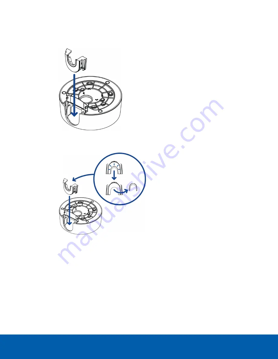
4. Depending on the conduit used, make the required adjustments to the side cable entry hole:

l

If you are using a 1/2" or 20 mm interior conduit, install the provided side conduit cover on to
the mounting adapter.

l

If using ¾” or 25 mm interior conduit, remove the center knockout piece on the provided side
conduit cover then install the side conduit cover on to the mounting adapter.

Mounting the Dome Camera Using the Side Cable Entry

16

Summary of Contents for Avigilon 1.3C-H5SL-D1

Page 1: ...e Avigilon H5SL Dome Camera Models 1 3C H5SL D1 1 3C H5SL D1 IR 1 3C H5SL DO1 IR 2 0C H5SL D1 2 0C H5SL D1 IR 2 0C H5SL DO1 IR 3 0C H5SL D1 3 0C H5SL D1 IR 3 0C H5SL DO1 IR 5 0C H5SL D1 5 0C H5SL D1 IR 5 0C H5SL DO1 IR ...

Page 2: ...t or other intellectual property rights of Avigilon Corporation or its licensors Disclaimer This document has been compiled and published using product descriptions and specifications available at the time of publication The contents of this document and the specifications of the products discussed herein are subject to change without notice Avigilon Corporation reserves the right to make any such...

Page 3: ...oE that is a Limited Power Source or LPS rated 48 VDC 5W min l The H5SL DO product is intended to be supplied by Power over Ethernet PoE that is a Limited Power Source or LPS rated 48 VDC 8W min l Any external power supply connected to this product may only be connected to another Avigilon product of the same model series External power connections must be properly insulated l Do not connect direc...

Page 4: ...e or more of the following measures l Reorient or relocate the receiving antenna l Increase the separation between the equipment and the receiver l Connect the equipment into an outlet on a circuit different from that to which the receiver is connected l Consult the dealer or an experienced radio TV technician for help Changes or modifications made to this equipment not expressly approved by Avigi...

Page 5: ...the Dome Cover 13 Inserting Cables through the Sealing Grommet 13 Using the Surface Mount Adapter 14 Mounting the Dome Camera Using the Bottom Cable Entry 14 Mounting the Dome Camera Using the Side Cable Entry 15 Mounting the Dome Camera to an Electrical Box 18 Installing the Camera Base to the Mounting Adapter 19 Installing the Dome Cover 20 In Ceiling Mount Installation 21 Required Tools and Mat...

Page 6: ...e Camera 39 Optional Using the USB Wi Fi Adapter 39 Assigning an IP Address 39 Accessing the Live Video Stream 40 Aiming the Dome Camera 40 Optional Configuring microSD Card Storage 41 Zooming and Focusing the Dome Camera 42 Configuring the Camera 42 Setting the IP Address Using the ARP Ping Method 42 For More Information 43 Connecting to External Audio and I O Devices 44 Connection Status LED Ind...

Page 7: ...r communication and image data transmission also occur over this connection 3 Link LED indicator Indicates if there is an active connection in the Ethernet port 4 Connection status LED indicator Provides information about device operation For more information see Connection Status LED Indicator on page 45 5 microSD card slot Accepts a microSD card for onboard storage For more information see Optio...

Page 8: ...output and audio devices 3 Micro USB port Accepts a micro USB to USB adapter Only required when using the Avigilon USB Wi Fi Adapter 4 Tilt lock thumb screw Provides a locking mechanism for the image tilt adjustment 5 Serial number tag Device information product serial number and part number label 6 I O Cable Management Clip Clip to help secure the I O cable in place Camera Base Rear View 2 ...

Page 9: ... for camera operation 2 Lanyard anchor The safety lanyard attaches to the anchor to prevent the camera from falling during installation 3 Vent Vent to allow moisture vapor to escape the sealed housing and equalize pressure Only available on H5SL DO models Camera Base Bottom View 3 ...

Page 10: ...ers for H5SL D models are not vandal resistant 2 Surface mount adapter Used to mount the dome camera to a wall ceiling or electrical box 3 Tamper resistant screws Star shaped captive screws to fix the dome cover to the base 4 Side cable entry cover Covers the side cable entry hole Cover View Surface Mount 4 ...

Page 11: ... clips Snaps to hold camera module during installation 3 Cable entry hole An entry hole for the cables required for camera operation 4 Mounting holes Holes for mounting the adapter to the following A UK standard single gang box B Octagon gang box D US standard single gang box Mounting Adapter View Surface Mount 5 ...

Page 12: ...ra to a wall ceiling or electrical box 2 Dome cover Vandal resistant dome cover Only available on H5SL DO models Dome covers for H5SL D models are not vandal resistant 3 Tamper resistant screws Star shaped captive screws to fix the dome cover to the base Cover View In Ceiling Mount 6 ...

Page 13: ...era module during installation 2 Lanyard Connects to the lanyard anchor on the camera base 3 Clamps Manually adjustable clamps for securing the dome camera to the ceiling 4 Clamp retainer Used to hold the clamps together before installation Mounting Adapter View In Ceiling Mount 7 ...

Page 14: ...pendant installations 2 NPT adapter Used to mount the dome camera to NPT pipes 3 Tamper resistant screws Star shaped captive screws to fix the dome cover to the base 4 Dome cover Vandal resistant dome cover Only available on H5SL DO models Dome covers for H5SL D models are not vandal resistant Cover View Pendant WallMount 8 ...

Page 15: ...s Snaps to hold camera module during installation 2 Lanyard Connects to the lanyard anchor on the camera base 3 1 1 2 NPT thread mount Standard male 1 1 2 NPT thread mount for mounting the dome camera to a pole or bracket NPT Adapter View Pendant Mount 9 ...

Page 16: ...nts for mounting the pendant wall mount bracket to a mounting surface 2 Mounting tabs Tabs for placing the pendant wall mount onto the bracket 3 Mounting points Points for securing the pendant wall mount to the mounting bracket Pendant WallMount Bracket View 10 ...

Page 17: ...nt Female NPS thread mount for pendant camera installations 2 Pendant wall mount screws Screws for securing the pendant wall mount to the mounting bracket 3 NPT pipe entry hole A 3 4 NPT threaded hole for NPT pipe conduits Pendant WallMount View 11 ...

Page 18: ...del H5SL D o Mounting template sticker o 4 screws and anchors for solid walls o Surface mount adapter o Side conduit cover o T20 Pin In star shaped driver l Avigilon H5SL Dome Camera Outdoor model H5SL DO o Mounting template sticker o RJ 45 grommet piercing cap o 4 screws and anchors for solid walls o Surface mount adapter o Side conduit cover o Side conduit plate 2 sizes o Conduit grommet o Cable...

Page 19: ...the dome cover to the camera base Inserting Cables through the Sealing Grommet Always use the provided sealing grommet to prevent dust and debris from entering the camera 1 Remove the sealing grommet from the camera base 2 Push the Ethernet cable through the grommet If you are installing the indoor model H5SL D you should be able to simply push the cable crimped or uncrimped through the grommet by...

Page 20: ...a different way use one of the other mounting adapter options and refer to their sections in this manual for more information l In ceiling mounting adapter H4SL MT DCIL For more information see In Ceiling Mount Installation on page 21 l Pendant NPT mounting adapter H4SL MT NPTA For more information see Pendant Mount Installation on page 29 o Pendant wall mounting adapter CM MT WALL must be used wi...

Page 21: ... Using the Side Cable Entry Perform the following steps if you will be mounting to a surface with the required cables coming out of an external conduit pipe Use this procedure if the mounting surface cannot be easily cut or when cables must be brought along the outside of the mounting surface 1 Use the mounting template to drill four mounting holes into the mounting surface Make sure the mounting ...

Page 22: ... or 20 mm interior conduit install the provided side conduit cover on to the mounting adapter l If using or 25 mm interior conduit remove the center knockout piece on the provided side conduit cover then install the side conduit cover on to the mounting adapter Mounting the Dome Camera Using the Side Cable Entry 16 ...

Page 23: ...g adapter over the conduit and plate assembly Ensure the plate is compatible with the type of conduit used If you are installing the outdoor model H5SL DO you may need to cut off part of the rubber gasket on the mounting adapter to make room for the plate Mounting the Dome Camera Using the Side Cable Entry 17 ...

Page 24: ...required cables through the cable entry hole Make sure the cables are threaded through the sealing grommet from the camera base For more information see Inserting Cables through the Sealing Grommet on page 30 2 Use pan head screws to install the mounting adapter to the electrical box Select the hole configuration that matches the electrical box shape A UK standard single gang box B Octagon gang bo...

Page 25: ...le 4 Connect the network cable to the Ethernet port The Link LED will turn on once a network link has been established 5 If external input or output devices or audio devices are part of the installation for example door contacts relays microphone etc connect the devices to the I O connector block For more information see Connecting to External Audio and I O Devices on page 44 6 Align the large ora...

Page 26: ...a covers the required field of view For more information see l Connecting to the Camera on page 39 l Aiming the Dome Camera on page 40 l Zooming and Focusing the Dome Camera on page 42 1 Attach the dome cover to the base by tightening the screws with the star shaped driver 2 Remove the protective cover on the outside of the dome bubble Installing the Dome Cover 20 ...

Page 27: ...e sticker l 4 screws and anchors for solid walls l Surface mount adapter l Side conduit cover l Avigilon H5SL Dome Camera Outdoor model H5SL DO o RJ 45 grommet piercing cap o T20 Pin In star shaped driver o Provided accessories that are not required for this installation l Mounting template sticker l 4 screws and anchors for solid walls l Surface mount adapter l Side conduit cover l Side conduit p...

Page 28: ...the dome cover to the camera base Inserting Cables through the Sealing Grommet Always use the provided sealing grommet to prevent dust and debris from entering the camera 1 Remove the sealing grommet from the camera base 2 Push the Ethernet cable through the grommet If you are installing the indoor model H5SL D you should be able to simply push the cable crimped or uncrimped through the grommet by...

Page 29: ... Push any other required cables through the grommet Note If you pull multiple cables through the sealing grommet apply silicone sealant to seal any gaps in the grommet Using the In Ceiling Mounting Adapter If the dome camera needs to be installed into a ceiling you can discard the surface mount adapter that is provided with the dome camera and use the in ceiling mounting adapter instead H4SL MT DC...

Page 30: ...plate to cut an entry hole for the camera into the ceiling 2 Insert the in ceiling mounting adapter into the entry hole then pull the sealing grommet with the required cables through the adapter Using the In Ceiling Mounting Adapter 24 ...

Page 31: ...3 Pull off the clamp retainer holding the clamps in place 4 Push the orange clamp handles up so that the metal arms extend outside the mounting adapter Using the In Ceiling Mounting Adapter 25 ...

Page 32: ...inch the clamp down until the clamp is secured 6 Repeat the previous step on the other side Make sure both clamps are level and horizontal Installing the Camera Base to the Mounting Adapter After you install the mounting adapter mount the camera base to the adapter Installing the Camera Base to the Mounting Adapter 26 ...

Page 33: ...e inside and outside of the cable entry hole 4 Connect the network cable to the Ethernet port The Link LED will turn on once a network link has been established 5 If external input or output devices or audio devices are part of the installation for example door contacts relays microphone etc connect the devices to the I O connector block For more information see Connecting to External Audio and I ...

Page 34: ...recommend that you first connect to the camera and adjust the aim zoom and focus so that the camera covers the required field of view For more information see l Connecting to the Camera on page 39 l Aiming the Dome Camera on page 40 l Zooming and Focusing the Dome Camera on page 42 1 Attach the dome cover to the base by tightening the screws with the star shaped driver 2 Remove the protective cove...

Page 35: ...for solid walls l Surface mount adapter l Side conduit cover l Avigilon H5SL Dome Camera Outdoor model H5SL DO o RJ 45 grommet piercing cap o T20 Pin In star shaped driver o Provided accessories that are not required for this installation l Mounting template sticker l 4 screws and anchors for solid walls l Surface mount adapter l Side conduit cover 2 sizes l Side conduit plate 2 sizes Ensure the N...

Page 36: ...te Be careful not to scratch or touch the dome bubble The resulting marks or fingerprints may affect the overall image quality Keep the protective covers on the outside of the dome bubble until the installation is complete l Remove the dome cover by releasing the elastic strap holding the dome cover to the camera base Inserting Cables through the Sealing Grommet Always use the provided sealing gro...

Page 37: ...push the cable through the grommet Ensure that the orientation of the cable and grommet matches the one shown in the image 3 Push any other required cables through the grommet Note If you pull multiple cables through the sealing grommet apply silicone sealant to seal any gaps in the grommet Mounting the Dome Camera to a Pipe If the dome camera needs to be installed to a pipe for a pendant installa...

Page 38: ...e to female pipe adapter c Lock nut d NPT adapter Optional Mounting the Dome Camera to the Pendant Wall Mount If the dome camera will be using the pendant wall mount you will need to install the NPT adapter as well 1 Determine where the cables will enter the pendant wall mount l If the cables will be pulled from inside the mounting surface use the cable entry hole at the rear of the pendant wall m...

Page 39: ...cket to the mounting surface 4 Insert the pendant wall mount over the bracket mounting tabs 5 Pull the required cables through the preferred cable entry hole on the pendant wall mount l If you are using the pipe entry hole pull the cables through the pipe conduit then the wall mount Next apply thread seal tape to the pipe conduit and screw it into the pipe entry hole Optional Mounting the Dome Cam...

Page 40: ...6 Tighten the wall mount screws to secure the wall mount to the bracket Use the T20 star shaped key provided in the camera package Optional Mounting the Dome Camera to the Pendant WallMount 34 ...

Page 41: ... nut onto the NPT adapter then secure the NPT adapter into the pendant wall mount 8 Carefully tighten the lock nut until the NPT adapter is secured to the wall mount Optional Mounting the Dome Camera to the Pendant WallMount 35 ...

Page 42: ...y seated on the inside and outside of the cable entry hole 4 Connect the network cable to the Ethernet port The Link LED will turn on once a network link has been established 5 If external input or output devices or audio devices are part of the installation for example door contacts relays microphone etc connect the devices to the I O connector block For more information see Connecting to Externa...

Page 43: ...stalling the dome cover we recommend that you first connect to the camera and adjust the aim zoom and focus so that the camera covers the required field of view For more information see l Connecting to the Camera on page 39 l Aiming the Dome Camera on page 40 l Zooming and Focusing the Dome Camera on page 42 Installing the Dome Cover 37 ...

Page 44: ...1 Attach the dome cover to the base by tightening the screws with the star shaped driver 2 Remove the protective cover on the outside of the dome bubble Installing the Dome Cover 38 ...

Page 45: ...evice automatically obtains an IP address when it is connected to a network Note If the device cannot obtain an IP address from a DHCP server it will use Zero Configuration Networking Zeroconf to choose an IP address When set using Zeroconf the IP address is in the 169 254 0 0 16 subnet The IP address settings can be changed using one of the following methods l The mobile web interface using the U...

Page 46: ...ideo Management software application for example the Avigilon Control Center software Note The default device username is administrator with no password Aiming the Dome Camera Reference the camera s live stream as you aim the camera 1 Pan the lens until it is aimed in the correct direction If the camera stops panning before it reaches its final destination stop and pan the camera in the opposite d...

Page 47: ... ring to set the image to the correct angle 6 In the camera web browser interface or the Avigilon Control Center software adjust the camera s Image and Display settings Optional Configuring microSD Card Storage To use the camera s SD card storage feature you must insert a microSD card into the card slot It is recommended that the microSD card have a write speed of class 10 or better If the microSD...

Page 48: ...ar buttons to manually adjust the focus Configuring the Camera Once installed use one of the following methods to configure the camera l If you have the USB Wifi Adapter you can access the mobile web interface to configure the camera For more information see Avigilon USB Wi Fi Adapter System User Guide l If you have installed multiple cameras you can use the Avigilon Camera Configuration Tool to c...

Page 49: ... 78 b ping l 123 t New Camera IP Address For example ping l 123 t 192 168 1 10 3 Reboot the camera 4 Close the Command Prompt window when you see the following message Reply from New Camera IP Address For More Information Additional information about setting up and using the device is available in the following guides l Avigilon Control Center Client User Guide l Web Interface User Guide Avigilon ...

Page 50: ...ower Source or LPS rated 48 VDC 8 W min External audio and I O devices are connected to the camera through the audio and I O terminal block The pinout for the terminal block is shown in the following diagram 1 Audio Output line level An external power amplifier should be used when connecting speakers and microphones as shown in the diagram 2 Audio Ground 3 Audio Input line level 4 Ground 5 Digital...

Page 51: ...tempting to obtain an IP address Discoverable Two short flashes every second Obtained an IP address but not connected to the Network Video Management software Upgrading Firmware Two short flashes and one long flash every second Updating the firmware Connected On Connected to the Network Video Management software or an ACC Server The default connected setting can be changed to Off using the camera ...

Page 52: ...ocate the small orange arrows that point at the camera housing clips 3 Insert a flat head screwdriver or grommet piercing cap against one of the camera housing clips 4 Lever one side of the camera base out of the clip 5 Lift the camera base out of the adapter Removing the Dome Camera from the Mounting Adapter 46 ...

Page 53: ...n to reset the device The firmware revert button is shown in the following diagram 1 Ensure the device is powered on 2 Using a straightened paperclip or similar tool gently press and hold the firmware revert button 3 Release the button after three seconds CAUTION Do not apply excessive force Inserting the tool too far may damage the camera Resetting to Factory Default Settings 47 ...

Page 54: ... Avigilon warranty terms for this product are provided at avigilon com warranty Warranty service and technical support can be obtained by contacting Avigilon Technical Support avigilon com contact us Limited Warranty and TechnicalSupport 48 ...

Reviews: