background image

Hardware Installation

5

2.3.1    Antenna Options

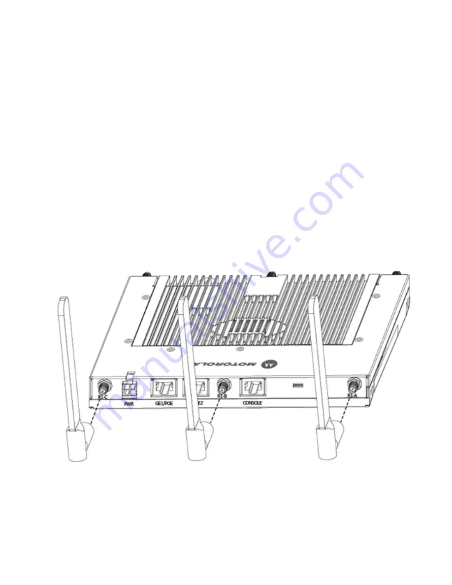
Motorola supports two antenna suites for AP-7131 and AP-7131N models. One antenna suite 
supporting the 2.4 GHz band and another antenna suite supporting the 5 GHz band. Select an antenna 
model best suited to the intended operational environment of your access point. The AP-7131N model 
access point can be purchased in a three radio configuration. If a three radio SKU is purchased, the 
access point ships with a single antenna, factory connected, to the access point chassis (next to the 
existing R1-A connector). This antenna is in addition to the other six antennas available to the access 
point’s other two radios. The single antenna supporting the AP-7131N’s third radio supports sensor 
mode only and can not function as a WLAN radio.

Antenna connectors for single radio model access points are located on the same side of the access 
point as the LAN and WAN port connections (GE1/POE and GE2). On single radio versions, the R-SMA 
connectors can support both bands and should be connected to a R-SMA dual-band antenna or an 
appropriate single band antenna. If necessary a R-SMA to R-BNC adapter (Part No. 25-72178-01) can 
be purchased separately from Motorola. 

R1 defines the access point’s radio 1 antenna connectors and R2 defines radio 2 antenna connectors.

Certain Rogue AP Detection features use a radio to perform dual-band scanning. The dedicated radio 
should be connected to an appropriate dual-band dipole antenna (Part No. ML-2452-APA2-01).

Summary of Contents for AP-7131 Series

Page 1: ...INSTALLATION AP 7131 Series Access Point Installation Guide ...

Page 2: ......

Page 3: ...7131 9 2 5 LED Indicators 19 3 0 Basic AP 7131 Configuration 24 3 1 Resetting the Access Point s Password 26 3 2 Configuring Basic Device Settings 26 3 3 Where to Go From Here 37 4 0 Specifications 38 4 1 AP 7131 Physical Characteristics 38 4 2 AP 7131N Physical Characteristics 38 4 3 Electrical Characteristics 39 4 4 AP 7131 Radio Characteristics 39 4 5 AP 7131N Radio Characteristics 40 Contents ...

Page 4: ...5 0 Regulatory Compliance 41 6 0 Waste Electrical and Electronic Equipment WEEE 47 7 0 Motorola s Enterprise Mobility Support Center 49 8 0 AP 7131 Series ROHS Compliance 50 ...

Page 5: ... Logo are registered in the US Patent Trademark Office Symbol is a registered trademark of Symbol Technologies Inc All other product or service names are the property of their respective owners Motorola Inc 2010 All rights reserved ...

Page 6: ......

Page 7: ...ervices at the local or remote site All traffic between the adaptive access points and the wireless switch is secured though an IPSec tunnel Additionally compatibility with Motorola s RF Management Suite RFMS allows you to centrally plan deploy monitor and secure large deployments With the introduction of the AP 7131 4 x firmware baseline Motorola is also introducing a new series of AP 7131N model...

Page 8: ...spaces Do not install this equipment or work with its power circuits during thunderstorms or other weather conditions that could cause a power surge Verify there is adequate ventilation around the device and that ambient temperatures meet equipment operation specifications 1 3 Site Preparation Consult your site survey and network analysis reports to determine specific equipment placement power dro...

Page 9: ...t has a continuous temperature range between 20 C to 50 C 2 2 Package Contents Check package contents for the correct model AP 7131 and applicable AP 7131 accessories Each available configuration at a minimum contains AP 7131 or AP 7131N model access point accessories dependent on SKU ordered AP 7131 Series Install Guide this guide supporting both AP 7131 and AP 7131N models Wall mount screw and a...

Page 10: ...t find an area lit from far away to be not bright enough An area lit sharply might minimize coverage and create dark areas Uniform antenna placement in an area like even placement of a light bulb provides even efficient coverage Place the access point using the following guidelines Install the access point at an ideal height of 10 feet from the ground Orient the access point antennas vertically fo...

Page 11: ... other two radios The single antenna supporting the AP 7131N s third radio supports sensor mode only and can not function as a WLAN radio Antenna connectors for single radio model access points are located on the same side of the access point as the LAN and WAN port connections GE1 POE and GE2 On single radio versions the R SMA connectors can support both bands and should be connected to a R SMA d...

Page 12: ...l Antenna 3 3 ML 2499 BYGA2 01R Yagi Antenna 13 9 ML 2452 APA2 01 Dual Band 3 4 ML 2452 PTA2M3X3 1 Facade with 6 Element Antenna Module 4 75 5 5 ML 2452 PTA3M3 036 3 Port MIMO Antenna 5 5 NOTE An additional adapter is required to use ML 2499 11PNA2 01R and ML 2499 BYGA2 01R model antennas Please contact Motorola for more information Part Number Antenna Type Approximate Gain dBi ML 5299 WPNA1 01R P...

Page 13: ...eparately as an accessory If the access point is provided both POE power over the GE1 POE connection as well as the 50 14000 247R power supply concurrently the access point will source power from the 50 14000 247R supply only Disconnecting AC power from the 50 14000 247R causes the AP to re boot before sourcing power from the POE power injector If the AP is operating using injector supplied power ...

Page 14: ... from excessive heat humidity vibration and dust The Power Injector isn t a repeater and does not amplify the Ethernet signal For optimal performance ensure the Power Injector is placed as close as possible to the data port To install the Power Injector to an Ethernet data source and an access point CAUTION To avoid problematic performance and restarts disable POE from a wired switch port connecte...

Page 15: ...llowing mounting options based on the physical environment of the coverage area Do not mount the access point in a location that has not been approved in a site survey 2 4 1 Wall Mounting Wall mounting requires hanging the access point along its width or length using the pair of slots on the bottom of the unit and the access point mounting template on the next page for the screws The hardware and ...

Page 16: ...AP 7131 Series Access Point Installation Guide 10 ...

Page 17: ...unting screw and stop when there is 1mm between the screw head and the wall If pre drilling a hole the recommended hole size is 2 8mm 0 11in if the screws are going directly into the wall and 6mm 0 23in if wall anchors are being used 6 If required install and attach a security cable to the access point lock port 7 Attach the antennas to their correct connectors 8 For information on available anten...

Page 18: ...e information on using the Power Injector see Power Injector System on page 7 For standard power adapter non Power Injector and line cord installations a Connect a RJ 45 CAT5e or CAT6 Ethernet cable between the network data supply host and the access point s GE1 POE or GE2 port b Verify the power adapter is correctly rated according the country of operation c Connect the power supply line cord to ...

Page 19: ...the antennas available to the access point see Antenna Options on page 5 4 Cable the access point using either the Power Injector solution or an approved line cord and power supply For Motorola Power Injector installations a Connect a RJ 45 CAT5e or CAT6 Ethernet cable between the network data supply host and the Power Injector Data In connector b Connect a RJ 45 CAT5e or CAT6 Ethernet cable betwe...

Page 20: ...access point e Attach the power supply line cord to a power supply 5 Verify the behavior of the access point LEDs For more information see LED Indicators on page 19 6 Align the bottom of the ceiling T bar with the back of the access point 7 Orient the access point chassis by its length and the length of the ceiling T bar 8 Rotate the access point chassis 45 degrees clockwise 9 Push the back of the...

Page 21: ...the ceiling installation requires placing the access point above a suspended ceiling and installing the provided light pipe under the ceiling tile for viewing the rear panel status LEDs of the unit An above the ceiling installation enables installations compliant with drop ceilings suspended ceilings and industry standard tiles from 625 to 75 inches thick NOTE If the access point is utilizing remo...

Page 22: ...roper access point operation within the Air Handling Plenum the access point must be installed with the bottom surface of the unit in contact with the un finished surface of the ceiling tile This will facilitate the positioning of the light pipe described in the following pages through the ceiling tile CAUTION Motorola does not recommend mounting the access point directly to any suspended ceiling ...

Page 23: ...f the badge and slide the badge onto the light pipe from the finished side of the tile 11 Attach the antennas to their correct connectors For information on the antennas available to the access point see Antenna Options on page 5 12 Motorola recommends attaching safety wire to the access point safety wire tie point or security cable if used to the access point s lock port CAUTION Motorola recommen...

Page 24: ...nformation on using the Power Injector see Power Injector System on page 7 For standard power adapter non Power Injector and line cord installations a Connect a RJ 45 Ethernet cable between the network data supply host and the access point s GE1 POE or GE2 port b Verify the power adapter is correctly rated according the country of operation c Connect the power supply line cord to the power adapter...

Page 25: ...LED is exercised during startup to allow the user to see if an LED is non functional The LEDs turn on and off while rotating around in a circle Since two LEDs feed each light pipe the pattern is from left to right then right to left The LEDs on the top housing of the access point are clearly visible in wall and below ceiling installations The top housing LEDs have the following display and functio...

Page 26: ...D alternates between Amber and Yellow The blink interval is 0 5 seconds It s 1 second whenno Server is connected Blinking Emerald indicates 802 11bg activity A 5 second Emerald and Yellow blink rate defines 802 11bgn activity A 2 second Emerald and Yellow blink rate defines 802 11bgn 40 MHz activity When functioning as a sensor LED alternates between Emerald and Yellow The blink interval is 0 5 se...

Page 27: ...ond Amber and Yellow blink rate defines 802 11an activity A 2 second Amber and Yellow blink rate defines 802 11an 40 MHz activity When functioning as a sensor LED alternates between Amber and Yellow The blink interval is 0 5 seconds It s 1 second whenno Server is connected Blinking Emerald indicates 802 11bg activity A 5 second Emerald and Yellow blink rate defines 802 11bgn activity A 2 second Em...

Page 28: ...iagnostic mode White defines normal operation Green defines normal GE1 operation Green defines normal GE2 operation Off Blinking Emerald indicates 802 11bg activity A 5 second Emerald and Yellow blink rate defines 802 11bgn activity A 2 second Emerald and Yellow blink rate defines 802 11bgn 40 MHz activity When functioning as a sensor LED alternates between Emerald and Yellow The blink interval is...

Page 29: ...c mode White defines normal operation Green defines normal GE1 operation Green defines normal GE2 operation Blinking Amber indicates 802 11aactivity A 5 second Amber and Yellow blink rate defines 802 11an activity A 2 second Amber and Yellow blink rate defines 802 11an 40 MHz activity When functioning as a sensor LED alternates between Amber and Yellow The blink interval is 0 5 seconds It s 1 seco...

Page 30: ...ault WAN IP address is 10 1 1 1 For optimal viewing of the Web UI the screen resolution should be set to 1024 x 768 pixels or greater 1 Start a browser and enter the following IP address in the address field https 10 1 1 1 LED 7 Blinking Red 160 msec indicates a failure condition Solid Red defines the diagnostic mode White defines normal operation NOTE For advanced configuration options beyond the...

Page 31: ...motorola as the default password If the default login is successful the Change Admin Password window displays 3 Change the password Enter the current password and a new admin password in fields provided and click Apply Once the admin password has been updated a warning message displays stating the ...

Page 32: ...ick Setup screen the values also change within the screen where these parameters also exist Additionally if the values are updated in these other screens the values initially set within the Quick Setup screen will be updated To define a basic access point configuration NOTE Though the access point can have its basic settings defined using a number of different screens Motorola recommends using the...

Page 33: ... title for this access point The System Name is useful if multiple devices are being administered NOTE Beginning with the 4 0 release of the access point firmware WIPS functionality is no longer configured within a designated WIPS screen The WIPS Server designation and radio configuration is now defined as part of the access point s quick setup For a description of WIPS functionality and how it re...

Page 34: ...mary and secondary WIPS console server WIPS support requires a Motorola AirDefense WIPS Server on the network WIPS functionality is not provided by the access point alone The access point works in conjunction with the dedicated WIPS server s 4 Refer to the new Radio Configuration field to define how WLAN and WIPS are supported by the access point s radio s Remember the options available depend on ...

Page 35: ...able Radio 1 WLAN Radio 2 WLAN Radio 1 WLAN Radio 2 WLAN Radio 3 Disabled Sensor only Spectrum Analysis mode no WLAN Radio 1 WIPS Radio 1 WIPS Radio 2 WIPS Radio 1 WIPS Radio 2 WIPS Radio 3 Disabled 2 4 GHz WLAN no Sensor Radio 1 WLAN B G N Radio1 WLAN Radio 2 Disabled Radio 1 WLAN Radio 2 Disabled Radio 3 Disabled 5 0 GHz WLAN no Sensor Radio 1 WLAN A N Radio1 Disabled Radio 2 WLAN Radio 1 Disabl...

Page 36: ... No connections to a larger network or the Internet will be possible MUs cannot communicate beyond the configured subnets b Select the This Interface is a DHCP Client checkbox to enable DHCP for the access point WAN connection This is useful if the target corporate network or Internet Service Provider ISP uses DHCP DHCP is a protocol that includes mechanisms for IP address allocation and delivery ...

Page 37: ...ata networks h Select the Keep Alive checkbox to enable occasional communications over the WAN port even when client communications to the WAN are idle Some ISPs terminate inactive connections while others do not In either case enabling Keep Alive maintains the WAN connection even when there is no traffic If the ISP drops the connection after the idle time the access point automatically reestablis...

Page 38: ...DNS Server numerical IP address g If using DHCP Server use the Address Assignment Range parameter to specify a range of IP address reserved for mapping clients to IP addresses If a manually static mapped IP address is within the IP address range specified that IP address could still be assigned to another client To avoid this ensure all statically mapped IP addresses are outside of the IP address ...

Page 39: ... results in all changes to the screens being lost unless you use the Un applied Changes pop up window to overwrite the current settings 10 Click Undo Changes if necessary to undo any changes made Undo Changes reverts the settings displayed on the Quick Setup screen to the last saved configuration CAUTION Only a qualified wireless network administrator should set the access point radio configuratio...

Page 40: ...y No authentication and No Encryption options selected Naming and saving such a policy as is would provide no security and might only make sense in a guest network wherein no sensitive data is either transmitted or received Consequently at a minimum a basic security scheme in this case WEP 128 is recommended 2 Ensure the Name of the security policy entered suits the intended configuration or funct...

Page 41: ...r proprietary routers and Motorola MUs use the same algorithm to convert an ASCII string to the same hexadecimal number Non Motorola clients and devices need to enter WEP keys manually as hexadecimal numbers The access point and its target client s must use the same pass key to interoperate Keys 1 4 Use the Key 1 4 fields to specify key numbers For WEP 64 40 bit key the keys are 10 hexadecimal cha...

Page 42: ...t only works with Motorola MUs Only use a Motorola MU to test connectivity using WNMP To ping a specific MU to assess its connection with an access point 1 Select Status and Statistics MU Stats from the menu tree 2 Select the Echo Test button from within the MU Stats Summary screen 3 Define the following ping test parameters 4 Click the Ping button to begin transmitting ping packets to the MU addr...

Page 43: ...able on the Motorola Web site at http support symbol com support product manuals do Refer to Chapter 4 to define System Settings beyond the scope of the Quick Setup screen configure access point device access set SNMP values log system events set the access point system time and import device firmware and configuration files See Chapter 5 for information on configuring the access point LAN and WAN...

Page 44: ... 79 cm Height Housing Metal plenum rated housing UL2043 Weight 2 22 lbs Operating Temperature 4 F to 122 F 20 C to 50 C Storage Temperature 40 F to 158 F 40 C to 70 C Humidity 5 to 95 RH non condensing Electrostatic Discharge 15kV air 8kV contact Dimensions 5 50 in Depth x 7 88 in Width x 1 38 in Height 14 cm Depth x 20 32 cm Width x 3 5 cm Height Housing Metal plenum rated housing UL2043 Weight 2...

Page 45: ...5825 MHz except channel 52 64 Channels 1 13 EU Channels 1 11 US Canada Channel 14 2484 MHz Japan only Actual operating frequencies depend on regulatory Data Rates Supported 802 11g 1 2 5 5 11 6 9 12 18 24 36 48 and 54Mbps 802 11a 6 9 12 18 24 36 48 and 54Mbps 802 11n MCS 0 15 up to 300Mbps Wireless Medium Direct Sequence Spread Spectrum DSSS Orthogonal Frequency Division Multiplexing OFDM Spatial ...

Page 46: ...18 24 36 48 and 54Mbps 802 11n MCS 0 15 up to 300Mbps Wireless Medium Direct Sequence Spread Spectrum DSSS Orthogonal Frequency Division Multiplexing OFDM Spatial multiplexing MIMO Network Standards 802 11a 802 11b 802 11g 802 3 802 11n Draft 2 0 Maximum Available Transmit Power Maximum available conducted transmit power per chain 2 4Ghz 23dBm Maximum available conducted transmit power all chains ...

Page 47: ...e regulations Country Approvals Regulatory markings are applied to the device signifying the radio s are approved for use in the following countries United States Canada Australia Japan and Europe Please refer to the Declaration of Conformity DoC for details of other country markings This is available at http www2 symbol com doc Note 1 For 2 4GHz Products Europe includes Austria Belgium Bulgaria C...

Page 48: ...isted to UL CSA 60950 1 and certified to IEC60950 1 and EN60950 1 with SELV outputs Use only a Motorola approved power supply Use of alternative power supply will invalidate any approval given to this device and may be dangerous Wireless Devices Countries Country Selection Select only the country in which you are using the device Any other selection will make the operation of this device illegal O...

Page 49: ... norme NMB 003 du Canada Devices using the 5 470 5 725 GHz band shall not be capable of transmitting in the band 5 60 5 65 GHz in Canada make sure that Canada is the country selected during setup to ensure compliance Radio Transmitters This device complies with RSS 210 of Industry Science Canada Operation is subject to the following two conditions 1 this device may not cause harmful interference a...

Page 50: ...onment it may cause radio interference Install and use the equipment according to the instruction manual Korea Warning Statement for Class B Other Countries Autstralia Use of 5GHz RLAN s in Australia is restricted in the following band 5 50 5 65GHz Brazil Regulatory declarations for AP7131N BRAZIL Note The certification mark applied to the AP7131N is for Restrict Radiation Equipment This equipment...

Page 51: ... electromagnetic radiation Mexico Restrict Frequency Range to 2 450 2 4835 GHz Taiwan NOTICE According to Administrative Regulations on Low Power Radio Waves Radiated Devices Article 12 Without permission granted by the DGT any company enterprise or user is not allowed to change frequency enhance transmitting power or alter original characteristic as well as performance to a approved low power rad...

Page 52: ... 秭赫頻帶內操作之無線資訊傳輸設備 限於室內使用 Korea For a radio equipment using 2400 2483 5MHz or 5725 5825MHz the following two expression should be displayed 1 This radio equipment can be interfered during operation 당해 무선설비는 운용 중 전파혼신 가능성이 있음 2 This radio equipment cannot provide a service relevant to the human life safety 당해 무선설비 는전파혼 신 가능성이 있으므로 인명안전과 관련된 서비스는 할 수 없습니다 ...

Page 53: ...lun aadressi http www symbol com environmental_compliance Español Para clientes en la Unión Europea todos los productos deberán entregarse a Symbol al final de su ciclo de vida para que sean reciclados Si desea más información sobre cómo devolver un producto visite http www symbol com environmental_compliance Français Clients de l Union Européenne Tous les produits en fin de cycle de vie doivent ê...

Page 54: ...er devolvidos à Symbol para reciclagem Para obter informações sobre como devolver o produto visite http www symbol com environmental_compliance Slovenski Za kupce v EU vsi izdelki se morajo po poteku življenjske dobe vrniti podjetju Symbol za reciklažo Za informacije o vraèilu izdelka obišèite http www symbol com environmental_compliance Suomi Asiakkaat Euroopan unionin alueella Kaikki tuotteet on...

Page 55: ...e or fax within the time limits set forth in support agreements If you purchased your Enterprise Mobility business product from a Motorola business partner contact that business partner for support Customer Support Web Sites Motorola s Support Central Web site located at http support symbol com support provides information and online assistance including developer tools software downloads product ...

Page 56: ...所售产 品中可能会也可能不会含有所有所列的部件 This table was created to comply with China RoHS requirements for Motorola s AP 7131 and AP 7131N model access points 有毒有害物质或元素 部件名称 Parts 铅 Pb 汞 Hg 镉 Cd 六价铬 Cr6 多溴联苯 PBB 多溴二苯醚 PBDE 金属部件 Metal Parts X O O O O O 电路模块 Circuit Modules X O O O O O 电缆及电缆组件 Cables and Cable Assemblies X O O O O O 塑料和聚合物部件 Plastic and Polymeric Parts O O O O O O 光学和光学组件 Optics and Optical Componen...

Page 57: ......

Page 58: ...MOTOROLA INC 1303 E ALGONQUIN ROAD SCHAUMBURG IL 60196 http www motorola com 72E 124099 01 Revision B September 2010 ...

Reviews: