


~83~
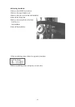
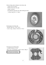
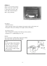
(E)Front wheel
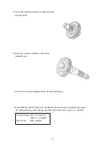
1.Remove the locking nut of the front
wheel on the right side.
2.Draw out the axle of front wheel,
remove the ring and take off the
gear sets of speedometer.
3.Remove the front wheel assy.
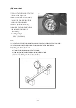
4.Assemble the front wheel follows
the opposite procedure of
dismantling.
Locking Torque:
M10: 3.0-4.0kg- m
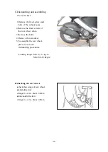
Note:
1.Put the lock block of speedometer gear assy upon the extrusion of the front fork.
2.Put the grease onto the grease sets of speedometer before assembling.
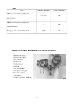
5.Checking the front wheel axle
a. Check the bending degree of the front axle.
b. Take note of the bending degree on the middle of axle.
c. Limit of use:Change it when above 0.2mm.
Summary of Contents for PA125
Page 10: ... 10 B CHASSIS Steel ball steering Front brake fluid Front brake cam ...
Page 12: ......
Page 33: ...33 1 Lubrication System Lubrication System Diagram ...
Page 42: ...42 42 2 Engine dismantling A Dismantling engine B lnstalling engine ...
Page 63: ... 63 7 A C Generator A Dismantling AC generator B Installing AC generator ...
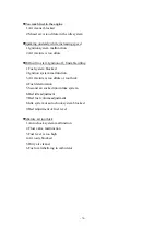
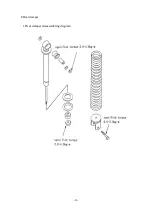
Page 92: ... 92 F Rear damper 1 Rear damper disassembling diagram ...
Page 99: ... 99 3 Recharge system 1 Recharge system diagram ...
Page 103: ... 103 5 Starting system 1 Starting wiring ...


