


~28~
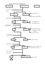
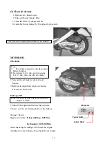
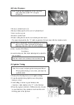
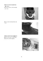
(8)Valve Clearance
1.Remove cylinder head cover.
2.Remove intake pipe from the cover of cylinder head.
3.Screw out the cap nut.
4.Remove cylinder head.
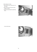
5.Rotate cooling fan, the mark on cam shaft gear must reach
The upper dead position, the “T” mark on generator fly must align with the crankcase mark.
l
Valve clearance:IN-0.08mm
Ex-0.08mm
l
Loosen locking nut, then rotate adjusting nut to adjust the
valve clearance.
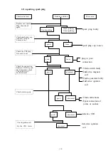
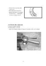
(9) Ignition Timing
1.Remove the checking hole cover of ignition timing.
2.Using the ignition timing light to assure the ignition
timing is correct.
3.Under idling, it means in good function when
crankcase’s mark matches to the “F” on the flywheel.
4.Raise the engine revolution to 5000 rpm slowly, it means
in good function, if the crankcase's mark matches with
Entering point of the flywheel.
Note: Checking and adjustment of valve clearance
only can be done under 35
o
C of engine
temperature.
Note: There is depressure reverse rotation device on cam
shaft. So never rotate cam shaft reversal when
adjusting, otherwise valve can not be adjusted.
Note: Re-check valve clearance after lock the nut.
Note: It is no need to adjust ignition timing and CDI set.
When ignition timing is not correct, just check the
ignition system.
Summary of Contents for PA125
Page 10: ... 10 B CHASSIS Steel ball steering Front brake fluid Front brake cam ...
Page 12: ......
Page 33: ...33 1 Lubrication System Lubrication System Diagram ...
Page 42: ...42 42 2 Engine dismantling A Dismantling engine B lnstalling engine ...
Page 63: ... 63 7 A C Generator A Dismantling AC generator B Installing AC generator ...
Page 92: ... 92 F Rear damper 1 Rear damper disassembling diagram ...
Page 99: ... 99 3 Recharge system 1 Recharge system diagram ...
Page 103: ... 103 5 Starting system 1 Starting wiring ...