


~56~
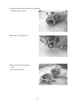
Check cam shaft
Check the convex surface and the height and see whether it has
Been damaged.
Check camshaft. If the bearing is loosen or worn out, change the whole set if necessary.
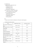
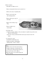
Check cam shaft holder
1.Check the cam shaft holder, cam rocker arm, and cam
Rocker arm shaft and see whether it is loosen or worn
out.
2.Cam shaft holder and cam rocker arm outer dia
measurement:
3.Cam rocker arm inner dia measurement:
4.Cam rocker arm shaft and rocker arm outer dia measurement:
5.Clearance between the Cam rocker arm and rocker arm shaft.
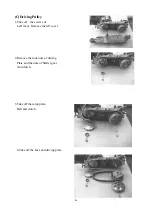
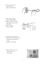
WHEN INSTALLING:
1.The mark “EX” on the cam shaft holder is the exhaust rocker arm, one-way stopper.
Install the exhaust rocker arm, the inlet rocker arm, and the rocket arm shaft.
2.Turn the flywheel to make the T mark pin correctly. The hole on the cam chain gear
should point upwards. Both the left and right concave points and the cylinder head are at
parallel position (convex part of cam shaft points upwards), then install the cam shaft on
the cylinder head.
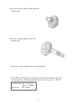
3.Install the cam chain onto the cam shaft gear.
4.Install the locking pin.
5.Install the camshaft holder, washer and nuts on the cylinder head.
6.Lock tightly the cylinder head nuts.
Locking torque: Cam shaft holder nuts:2.0kg- m
7.Adjust the valves clearance.
Limit of Use:
IN & EX:replace it below 25.90mm
NOTICE:
Do check if there is any damage on the cam rocker arm
Sliding surface.
Limit of use : replace it above 10.10mm.
Limit of use : replace it above 10.10mm.
Limit of use : replace it below 9.91mm.
Limit of use : replace it above 0.10mm.
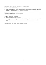
NOTICE:
a.The tangen angle of the heat side of intake valve’s rocker arm shaft is to match
with the bolt of the cam holder.
b.The tangent angle of the exhaust valve’s rocker arm shaft is to match with the bolt
of the cam holder.
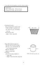
NOTICE:
a.Put some grease on the bolt thread of cam shaft holder
b.Lock the nuts of the cam shaft bracket in “cross” sequence for 2-3 times.
Summary of Contents for PA125
Page 10: ... 10 B CHASSIS Steel ball steering Front brake fluid Front brake cam ...
Page 12: ......
Page 33: ...33 1 Lubrication System Lubrication System Diagram ...
Page 42: ...42 42 2 Engine dismantling A Dismantling engine B lnstalling engine ...
Page 63: ... 63 7 A C Generator A Dismantling AC generator B Installing AC generator ...
Page 92: ... 92 F Rear damper 1 Rear damper disassembling diagram ...
Page 99: ... 99 3 Recharge system 1 Recharge system diagram ...
Page 103: ... 103 5 Starting system 1 Starting wiring ...


