background image

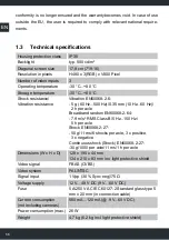
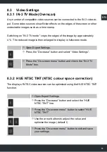
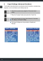
66

EN

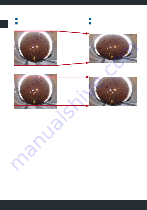
Original subject

  4:3 format

  Resolution H720 x V576

Monitor display

  16:9 format

  Resolution H800 x V480

PAL 480 only displays the 480 lines in the centre of the image. This gives a ver-
tical zoom factor of 1.2.

Note: 

Parts of the subject and video source overlays which are outside the central 480 
lines are lost in PAL 480 and not shown on the display.

PAL 480

PAL

Summary of Contents for MD3071A-V

Page 1: ...MD3071A V Heavy Duty Camera Solutions Bedienungs und Montageanleitung Installation and operating instructions Notice de montage et d utilisation ...

Page 2: ...2 ...

Page 3: ... 5 3 Videobild spiegeln 17 5 4 Helligkeit der Anzeige am Tag 18 5 5 Helligkeit der Anzeige und der Bedienelemente bei Nacht 19 5 6 Kontrast einstellen 20 5 7 Farbe einstellen 21 5 8 Standardeinstellungen wiederherstellen 22 6 Umschalten der Videoeingänge 23 6 1 Manuelles Umschalten 23 6 2 Automatisiertes Umschalten mit Steuerleitungen 23 6 3 Blinkerfunktion 24 6 4 Anhängerbetrieb konfigurieren 25 ...

Page 4: ...ispiele 38 11 1 LKW mit Rückraum und Seitenkamera blinkergesteuert 38 11 2 LKW und Anhänger mit Rückraumkamera 40 11 3 Winterdienst Fahrzeug mit einer Kamera und Kamerareinigungsanlage 42 11 4 LKW mit Rückraum und Seitenkamera plus 4 Kameras zur Ladungsüberwachung 44 11 5 LKW mit 360 Rundumsicht MVS Motec Mobile Vicinity Scout 46 12 Häufig gestellte Fragen 48 13 Störungen 50 14 Kundeninformationen...

Page 5: ...direkte Sicht zu erfassen Das Umschalten der Videoquellen erfolgt manuell oder mittels Steuerleitungen 1 1 Wichtige Hinweise zum Produkt Vergewissern Sie sich anhand der Angaben auf dem Typenschild des Monitors dass der Gerätetyp mit der vorliegenden Bedienungsanleitung übereinstimmt Weitere Hinweise entnehmen Sie bitte den Bedienungsanleitungen der ange schlossenen Kameras bzw Videosteuereinheit ...

Page 6: ...ckfestigkeit Vibrationsfestigkeit Schwingen EN60068 2 6 5 g 60 Hz 500 Hz 0 35 mm 10 Hz 60 Hz 2 h pro Achse Breitbandrauschen EN60068 2 64 7 9 m s2 RMS Klasse B 5 Hz 150 Hz 5 h pro Achse Schock EN60068 2 27 50 g 11 ms 6 Schocks pro Achse 3 x positiv 3 x negativ Dauerschock EN60068 2 27 30 g 1000 pro Achse 11 ms 1 h pro Achse Abmessungen B x H xT 128 x 195 x 44 mm 134 x 210 x 83 mm inkl Lichtschutzh...

Page 7: ...aben dieser Bedienungsanleitung erfolgen Die Geräte dürfen nur in Betrieb gesetzt werden wenn sich der Anwender über die aus der Benutzung resultierenden Risiken und Gefahren im Klaren ist Beschädigte Geräte dürfen nicht in Betrieb genommen werden Eine direkte Verbindung mit dem Wechselstromnetz ist unzulässig Die Sicherung darf nicht überbrückt oder entfernt werden Eine defekte Sicherung muss mit...

Page 8: ...m bzw nicht zugelassenem Zubehör sowie die Installation und der Betrieb des Gerätes können nicht überwacht werden Daher ist der Anwen der selbst für die korrekte Benutzung des Produktes verantwortlich Die gültigen Hersteller und Sicherheitsangaben der Maschine bzw des Fahrzeuges sind beim Einbau der Komponenten und während des Betriebes unbedingt zu be achten und einzuhalten Verlegen Sie die Kabel...

Page 9: ... der volle Funktionsumfang beschrieben Wurde der Moni tor bereits ab Werk applikationsspezifisch installiert bzw von einem Servicepart ner nachgerüstet so stehen gegebenenfalls nicht alle Funktionen zur Verfügung Entsprechend der gesetzten Berechtigungen und oder gewählten Betriebsart er scheinen nicht veränderbare Funktionen im Bildschirmmenü in grauer Schrift 3 1 Vor der Verwendung Entfernen Sie...

Page 10: ...altet die Bildschirmhelligkeit auf Tag oder Nachtbetrieb bzw Helligkeitsautomatik um Die Stärke der Absenkung kann im Bildschirmmenü konfiguriert werden Helligkeit Nacht Power Video Schaltet den Monitor mit kurzem Tastendruck EIN Schaltet den Monitor mit langem Tastendruck AUS Schaltet mit kurzem Tastendruck zwischen den Videoeingängen 1 2 und 3 um Leuchtet ROT wenn Betriebsspannung anliegt und de...

Page 11: ... über den Status des Schalt ausgangs Sensor Funktion Der Helligkeitssensor befindet sich auf der Gehäu sefront hinter den Streifen Damit der Sensor die Umgebungshelligkeit erfas sen kann muss er stets frei sein nicht abdecken 4 Monitor einschalten Der MD3071A V kann manuell und oder mit Hilfe von Steuerleitungen automa tisiert eingeschaltet werden Voraussetzung hierfür ist die Betriebsbereitschaft...

Page 12: ...ung ist eine fahrzeugseitige Anschaltung siehe Kapitel Appli kationsbeispiele Die POC Funktion muss im Menü aktiviert werden Drücken Sie die Taste Bildschirmmenü Es wird das Bildschirmmenü eingeblendet Drücken Sie wiederholt die Taste Kleiner und wählen Sie die Zeile POC aus Drücken Sie die Taste Bildschirmmenü und setzen Sie den Haken Drücken Sie die Taste Kleiner und wählen Sie die Zeile Schließ...

Page 13: ...tomatisch mit der Versorgungsspannung ein und lässt sich nicht manuell ausschalten 4 3 Automatisiertes Einschalten mit SEL 1 Steuerleitung IN 1 Der Monitor kann auch mittels der grünen SEL 1 Steuerleitung eingeschaltet werden Es wird das Bild vom Kameraeingang 1 IN 1 angezeigt Vorausset zung ist eine fahrzeugseitige Anschaltung siehe Kapitel Applikationsbeispiele In diesem Betriebszustand kann der...

Page 14: ...ie Taste Kleiner und wählen Sie die Zeile Schließen aus Drücken Sie die Taste Bildschirmmenü Das Bildschirmmenü wird geschlossen Wird keine Taste betätigt so wird das Menü nach ca 10 Se kunden automatisch geschlossen 5 2 Videosystem auswählen 5 2 1 PAL NTSC Auto Der Monitor MD3071A V unterstützt die Videosysteme PAL und NTSC Wählen Sie Auto im gemischten Betrieb d h wenn eine PAL und eine NTSC Kam...

Page 15: ...ner und wählen Sie die Zeile Schließen aus Drücken Sie die Taste Bildschirmmenü Das Bildschirmmenü wird geschlossen Wird keine Taste betätigt so wird das Menü nach ca 10 Se kunden automatisch geschlossen 5 2 2 PAL 480 Bedingt durch die Formatunterschiede zwischen der PAL Videoquelle Kamera 4 3 und dem Monitor LCD 16 9 wird das Motiv nicht formatrichtig dargestellt Außerdem ergibt sich ein Einfluss...

Page 16: ... PAL 480 werden nur die in der Bildmitte liegenden 480 Zeilen angezeigt Dadurch ergibt sich ein vertikaler Zoomfaktor von 1 2 Hinweis Motivanteile bzw Einblendungen der Videoquelle die außerhalb der inneren 480 Zeilen liegen gehen bei PAL 480 verloren und werden auf dem Display nicht dargestellt PAL 480 PAL ...
Page 17: ...ben unten tauschen Drücken Sie die Taste Bildschirmmenü Es wird das Bildschirmmenü eingeblendet Drücken Sie die Taste Kleiner und wählen Sie die Zeile Bildspiegelung aus Drücken Sie die Taste Bildschirmmenü zur Auswahl von Bildspiegelung Wählen Sie mit den Pfeiltasten die gewünschte Bildspiegelung aus Drücken Sie die Taste Bildschirmmenü und setzen Sie den Haken Drücken Sie die Taste Kleiner und w...

Page 18: ...llt wer den Drücken Sie die Taste Bildschirmmenü Es wird das Bildschirmmenü eingeblendet Drücken Sie die Taste Bildschirmmenü zur Auswahl von Helligkeit Tag Verändern Sie mit den Pfeiltasten den Wert zur Optimierung des Bildes Drücken Sie die Taste Bildschirmmenü zum Verlassen und Speichern der Einstellung Drücken Sie die Taste Kleiner und wählen Sie die Zeile Schließen aus Drücken Sie die Taste B...

Page 19: ...nzwert für die Helligkeits automatik Drücken Sie die Taste Bildschirmmenü Es wird das Bildschirmmenü eingeblendet Drücken Sie die Taste Kleiner und wählen Sie die Zeile Helligkeit Nacht aus Drücken Sie die Taste Bildschirmmenü zur Auswahl von Helligkeit Nacht Verändern Sie mit den Pfeiltasten den Wert zur Optimierung des Bildes Drücken Sie die Taste Bildschirmmenü zum Verlassen und Speichern der E...

Page 20: ...ldschirmmenü eingeblendet Drücken Sie die Taste Kleiner und wählen Sie die Zeile Kontrast aus Drücken Sie die Taste Bildschirmmenü zur Auswahl von Kontrast Verändern Sie mit den Pfeiltasten den Wert zur Optimierung des Bildes Drücken Sie die Taste Bildschirmmenü zum Verlassen und Speichern der Einstellung Drücken Sie die Taste Kleiner und wählen Sie die Zeile Schließen aus Drücken Sie die Taste Bi...

Page 21: ...ldschirmmenü eingeblendet Drücken Sie die Taste Kleiner und wählen Sie die Zeile Farbe aus Drücken Sie die Taste Bildschirmmenü zur Auswahl von Farbe Verändern Sie mit den Pfeiltasten den Wert zur Optimierung des Bildes Drücken Sie die Taste Bildschirmmenü zum Verlassen und Speichern der Einstellung Drücken Sie die Taste Kleiner und wählen Sie die Zeile Schließen aus Drücken Sie die Taste Bildschi...

Page 22: ...irmmenü eingeblendet Drücken Sie die Taste Kleiner und wählen Sie die Zeile Standardwerte aus Drücken Sie die Taste Bildschirmmenü zur Auswahl von Standardwerte Die Werte werden zurückgesetzt Drücken Sie die Taste Kleiner und wählen Sie die Zeile Schließen aus Drücken Sie die Taste Bildschirmmenü Das Bildschirmmenü wird geschlossen Wird keine Taste betätigt so wird das Menü nach ca 10 Sekunden aut...

Page 23: ... die Taste Power Video Der Monitor schaltet auf den jeweils nächsten Videoeingang um auch wenn dort kein Videosignal anliegt blauer Bild schirm IN 1 IN 2 IN 3 IN 1 IN 2 6 2 Automatisiertes Umschalten mit Steuerleitungen Mit den Steuerleitungen SEL 1 SEL 2 und SEL 3 können in Verbindung mit der Fahrzeugelektrik automatisierte Umschaltvorgänge realisiert werden siehe auch Kapitel Applikationsbeispie...

Page 24: ...erfunktion Die Blinkerfunktion ermöglicht die Nutzung der Anschlussleitung eines Fahrtrich tungsanzeigers Blinkerleitung als Steuerleitung für die Videosignal umschal tung Hierfür wird der Eingang IN 2 mit der Steuerleitung SEL 2 verwendet sie he auch Kapitel Applikationsbeispiele Damit die Umschaltung nicht im Takt des Blinkersignals erfolgt muss der Monitor wie folgt konfiguriert werden Drücken ...

Page 25: ...ten von Gespannen Sattel und Gliederzügen bei denen der Anhänger häufig an und abgekoppelt werden muss und sich damit der einzusehende Rückraum ändert Ziel ist es automatisch das erforderliche Kamerabild anzuzeigen Die Kamera der Zugmaschine wird stets am Videoeingang IN 1 angeschaltet Die Kamera des Anhängers bekommt den Videoeingang IN 2 Motec bietet hierfür spezielle Systemkabel für die Anschal...

Page 26: ...d setzen Sie den Haken Drücken Sie die Taste Kleiner und wählen Sie die Zeile Schließen aus Drücken Sie die Taste Bildschirmmenü Das Bildschirmmenü wird geschlossen Wird keine Taste betätigt so wird das Menü nach ca 10 Sekunden automa tisch geschlossen Zugmaschine solo Nach Einlegen des Rückwärtsgangs wird das Kamerabild der Zugmaschine IN 1 angezeigt Zugmaschine mit Anhänger Nach Einlegen des Rüc...

Page 27: ...it Sie als Schaltausgang genutzt werden kann muss sie als CTRL OUT 12 V konfiguriert sein siehe Kapitel Expert Set tings PIN 3 Mode Hinweis Das Bildschirmmenü muss geschlossen sein normaler Betriebszustand Drücken und halten Sie die Taste Kleiner zum temporären Einschalten Drücken Sie die Taste Größer zum dauerhaften Einschalten Drücken Sie die Taste Größer zum dauerhaften Ausschalten Der Schaltzu...

Page 28: ...Servicedienstleister o ä Personal bestimmt Öffnen Sie das Bildschirmmenü mit der Taste Bildschirmmenü Drücken Sie die Taste Größer und wählen Sie die Zeile Schließen aus Betätigen und halten Sie die Taste Bildschirmmenü für ca 3 Sekunden Die Expert Settings werden angezeigt Die Expert Settings sind ausschließlich in englischer und russischer Sprache verfügbar ...

Page 29: ...nn aktiv ange hakt oder inaktiv verriegelt werden Ein gesetzter Haken bedeutet dass der Anwender den Parameter im Hauptme nü verändern darf Öffnen Sie die Expert Settings Drücken Sie die Taste Kleiner und wählen Sie den zu verändernden Parameter aus Drücken Sie die Taste Bildschirmmenü und setzen Sie den entsprechenden Haken SEL 1 Priority Ist der Parameter SEL 1 Priority aktiv also der Haken gese...

Page 30: ...n Sie PIN 3 Mode Drücken Sie die Taste Bildschirmmenü zur Auswahl von PIN 3 Mode Drücken Sie die Taste Kleiner und wählen Sie die Zeile SEL 3 IN bzw CTRL OUT 12 V aus Drücken Sie die Taste Bildschirmmenü und setzen Sie den Haken Drücken Sie die Taste Kleiner und wählen Sie die Zeile Schließen aus Drücken Sie die Taste Bildschirmmenü Das Bildschirmmenü wird geschlossen Wird keine Taste betätigt so ...

Page 31: ...ettings Drücken Sie die Taste Kleiner und wählen Sie Video Settings aus Drücken Sie die Taste Bildschirmmenü und setzen Sie den Haken bei IN 3 TV Mode 8 3 2 HUE NTSC TINT NTSC Farbraumkorrektur Die Darstellung von NTSC Videoquellen kann mit Hilfe der HUE NTSC TINT Funktion optimiert werden Öffnen Sie die Expert Settings Drücken Sie die Taste Kleiner und wählen Sie die Zeile HUE NTSC TINT aus Drück...

Page 32: ... Blau Red Green Blue können einzeln verstärkt oder reduziert werden Öffnen Sie die Expert Settings Drücken Sie die Taste Kleiner und wählen Sie eine der Zeilen RED GREEN oder BLUE Level aus Drücken Sie die Taste Bildschirmmenü zur Auswahl des Farbkanals Verändern Sie mit den Pfeiltasten die Einstellungen so dass das Motiv farbrichtig angezeigt wird Hierzu eignen sich besonders weiße Bildanteile Dr...

Page 33: ...onitors zurückgesetzt Öffnen Sie die Expert Settings Drücken Sie die Taste Kleiner und wählen Sie Factory Settings aus Drücken Sie die Taste Bildschirmmenü Die Einstellungen werden nun zurückgesetzt Wählen Sie mit den Pfeiltasten die gewünschte Sprache aus Drücken Sie die Taste Bildschirmmenü zum Speichern der Einstellung Drücken Sie die Taste Kleiner und wählen Sie die Zeile Schließen aus Drücken...

Page 34: ...A V MH 1 mit RAM Halterung groß MD3071A V VK mit Kugelgelenk MD3071A V MH 3 mit RAM Halterung klein 200 02 000 52 MD SF 31 4 2 5x Ø 7 5 52 79 5 46 50 47 97 Ø R 85 100 54 GMF TFT M8 40 40 32 5 17 41 20002 00049 194 127 20002 00053 MD MS1 62 46 5 5 30 38 1 2 0 4 8 5 33 5 64 62 R19 46 2x M4x12 ULS RAM MH 1 MD MS1 17 8 41 20002 00049 194 127 MD3071A V RAM MH1 20002 00051 RAM MH 3 62 38 100 24 5 6 25 3...

Page 35: ... Videoeingang IN 3 können Videoquellen mit eigener Stromver sorgung angeschlossen werden z B Motec Videosteuereinheit der Baureihen MBxxxx MVCUxxxx und MVCDxxxx 10 1 Spannungsversorgung aus dem Fahrzeugbordnetz Der MD3071A V kann als Anzeige von bis zu 3 Videoquellen aus einem Fahr zeugbordnetz versorgt werden Anschluss P Der 6 polige Anschluss P beinhal tet auch die Steuerleitungen POC SEL 1 SEL ...

Page 36: ... 4 grün SEL 1 Steuerleitung Eingang 5 weiß SEL 2 Steuerleitung Eingang 6 gelb POC Steuerleitung Eingang IN 1 Kontakt Signal Buchse 4 polig Mini DIN Blick auf die Buchse am Monitor 1 Video 1 Eingang 2 SEL 12 Steuerleitung Eingang 3 SEL 13 Steuerleitung Eingang 4 12 V max 500 mA Versorgungsausgang 5 Schirm GND IN 2 Kontakt Signal Buchse 4 polig Mini DIN Blick auf die Buchse am Monitor 1 Video 2 Eing...

Page 37: ...gung gestellt werden muss Die Stromaufnahme über den Anschluss IN 3 ist monitorseitig auf 1 A begrenzt Höhere Ströme führen zum Abschalten des Monitors was durch eine rotblinkende Powertaste ange zeigt wird Der Anschluss erfolgt über vorkonfektionierte Motec Systemkabel z B MK73 xx IN 3 Kontakt Signal Buchse 9 polig Mini DIN Blick auf die Buchse am Monitor 1 VCC Nennspannung 12 V 48 V DC 9 V 60 V ...

Page 38: ...ollten Sie weiterführende Informationen oder Hilfe für ihre Ap plikation benötigen wenden Sie sich bitte an ihren Motec Kundenbetreuer oder an die Motec Servicehotline 11 1 LKW mit Rückraum und Seitenkamera blinkergesteuert Nach dem Einlegen des Rückwärtsgangs soll sich der Monitor automatisch einschalten und die Rückraumkamera anzeigen hohe Priorität Mit dem Fahrtrichtungsanzeiger rechter Blinker...

Page 39: ...able SEL 1 Priority Indicator IN 2 enable Trailer Mode Pin 3 Mode SEL 3 IN CTRL OUT 12 V Video Settings IN 3 TV Mode Anschlusskabel MD3071A AK rot 12 V 48 V CD Zündstartschalter 15 schwarz GND Bordnetz Minus 31 blau C T R L OUT 12 V SEL 3 grün SEL 1 Schaltsignal Rückwärtsgang weiß SEL 2 Fahrtrichtungs anzeiger rechts gelb POC Fahrtrichtungs anzeiger rechts MD3071A V P MD3071A AK IN 1 MKW Rückraumk...

Page 40: ...s Motor wagens angezeigt werden Ist der Anhänger angekoppelt soll der Rückraum des Anhängers angezeigt werden Nach dem Einlegen des Rückwärtsgangs soll sich der Monitor automatisch einschalten und die entsprechende Kamera anzeigen Bei angekoppeltem Anhänger soll die Deichsel temporär eingesehen werden können ...

Page 41: ...ator IN 2 enable Trailer Mode Pin 3 Mode SEL 3 IN CTRL OUT 12 V Video Settings IN 3 TV Mode Bei Verwendung des Kabelsets MK295 296 muss Anhänger SEL 23 aktiviert werden Anschlusskabel MD3071A AK rot 12 V 48 V CD Zündstartschalter 15 schwarz GND Bordnetz Minus 31 blau C T R L OUT 12 V SEL 3 grün SEL 1 Schaltsignal Rückwärtsgang weiß SEL 2 Schaltsignal Rückwärtsgang gelb POC MD3071A V P MD3071A AK I...

Page 42: ...k Dem Fahrer soll es möglich sein die Kamera auch während der Fahrt reinigen zu können Die Kamerareinigungsanlage soll vom Monitor aus bedient werden können Die Kamera soll automatisch mit dem Einlegen des Rückwärtsgangs angezeigt werden Rückraum Zur Anzeige von Rückraum Streubild und Räumergebnis wird der Monitor bei Bedarf manuell eingeschaltet Dauerbetrieb ...

Page 43: ...ngs Mirroring enable POC enable SEL 1 Priority Indicator IN 2 enable Trailer Mode Pin 3 Mode SEL 3 IN CTRL OUT 12 V Video Settings IN 3 TV Mode Anschlusskabel MD3071A AK rot 12 V 48 V CD Zündstartschalter 15 schwarz GND Bordnetz Minus 31 blau C T R L OUT 12 V SEL 3 Steuereingang Reinigungsanlage grün SEL 1 Schaltsignal Rückwärtsgang weiß SEL 2 gelb POC MD3071A V P MD3071A AK IN 1 MK25 MA2 Kamera I...

Page 44: ...lten und die Rückraumkamera anzeigen hohe Priorität Mit dem Fahrtrichtungsanzeiger rechter Blinker soll automatisch die Seitenraumkamera angezeigt werden mittlere Priorität Zur Überwachung des Laderaums wird der Monitor bei Bedarf manuell eingeschaltet niedrige Priorität Die 4 Kameras im Laderaum sollen gleichzeitig auf dem Monitor dargestellt werden Quad Bild ...

Page 45: ...cator IN 2 enable Trailer Mode Pin 3 Mode SEL 3 IN CTRL OUT 12 V Video Settings IN 3 TV Mode Anschlusskabel MD3071A AK rot 12 V 48 V CD Zündstartschalter 15 schwarz GND Bordnetz Minus 31 blau C T R L OUT 12 V SEL 3 Zündstartschalter 15 grün SEL 1 Schaltsignal Rückwärtsgang weiß SEL 2 Fahrtrichtungs anzeiger rechts gelb POC Fahrtrichtungs anzeiger rechts MD3071A V P MD3071A AK IN 1 MKW Rückraum kam...

Page 46: ...si aus der Vogelper spektive einsehen können Das Videosystem soll das Umfeld lückenlos auf dem Monitor anzeigen 360 Rundumsicht Zum Einsatz kommen 4 Kameras eine Videosteuereinheit MVCD1000 und ein MD3071A V MD3071A V F1 F2 F3 MVCD1000 MBE1000 20005 01113 IN 3 MC7180 MK722 MKS MKS MKS MKS MK723 MC7180 MC7180 MC7180 ...

Page 47: ... horizontal IN 3 vertikal Videosystem PAL NTSC Auto PAL480 Anhänger SEL 22 SEL 23 Blinker IN 2 POC Expert Settings Mirroring enable POC enable SEL 1 Priority Indicator IN 2 enable Trailer Mode Pin 3 Mode SEL 3 IN CTRL OUT 12 V Video Settings IN 3 TV Mode MD3071A V P IN 1 IN 2 IN 3 MK722 MVCD1000 ...

Page 48: ...ie ob die Sicherung im An schlusskabel funk tionstüchtig ist Wenn der Monitor nur über IN 3 ver sorgt wird dann sind die Funktionen Anhänger und Blin ker IN 2 nicht mög lich Der Monitor lässt sich mittels der gelben POC Leitung nicht einschal ten An der POC Leitung liegt kein Schaltsignal größer als 6 V an POC ist im Haupt menü nicht angehakt Überprüfen Sie das Schaltsignal Setzen Sie den Haken be...

Page 49: ...zontale und oder vertikale Bildspiege lung im Hauptmenü für jede Kamera separat Die Rückfahrkamera lässt sich am Monitor über die Power Taste wegschalten Der Monitor lässt sich beim Rückwärtsfahren abschalten Unfallrisiko Die Steuerleitung SEL 1 wurde nicht am Schaltsignal des Rückwärtsgangs angeschlossen Verwenden Sie die Steuerleitung SEL 1 da Sie die höchste Schaltpriorität hat Die Seitenraumka...

Page 50: ...49 6433 9145 9888 Service Fax 49 6433 9145 9877 Oberweyerer Str 21 service motec cameras com 65589 Hadamar Steinbach www motec cameras com GERMANY 15 Wartung Reinigung Der Monitor ist wartungsfrei Reinigen Sie den Bildschirm bei Bedarf mit einem weichen eventuell angefeuchteten Tuch Die Lüftungsschlitze des Monitors soll ten gelegentlich mit einem Tuch oder einem Pinsel von Staub befreit werden En...

Page 51: ...014 Spreizfuß MD SF 406 0089 034 Halteschraube für Spreizfuß GMF TFT 813 0055 007 17 Umweltschutz Die Verpackung besteht weitgehend aus wiederverwertbarem Material Nutzen Sie die Möglichkeit zum umweltgerechten Recyceln der Verpackung Altgeräte können zur umweltgerechten Entsorgung bei der nächstgelegenen Recycling stelle abgegeben oder an den Hersteller gesendet werden ...

Page 52: ...52 ...

Page 53: ...ystem 64 5 2 1 PAL NTSC Auto 64 5 2 2 PAL 480 65 5 3 Mirror video image 67 5 4 Daytime display brightness 68 5 5 Night time display and control brightness 69 5 6 Setting the contrast 70 5 7 Setting the colour 71 5 8 Restoring default settings 72 6 Switching the video inputs 73 6 1 Manual switching 73 6 2 Automatic switching with control lines 73 6 3 Indicator function 74 6 4 Configuring trailer mo...

Page 54: ... rear and side camera indicator activated 88 11 2 HGV and trailer with rear camera 90 11 3 Winter service vehicle with a camera and camera cleaning system 92 11 4 HGV with rear and side camera plus 4 cameras for 94 load area monitoring 94 11 5 Truck with 360 around view camera system 96 MVS Motec Mobile Vicinity Scout 96 12 Frequently Asked Questions 98 13 Faults 100 14 Customer information 100 15...

Page 55: ...sources can be switched manually or using control lines 1 1 Important information about the product Make certain based on the information on the monitor rating plate that the device type matches these operating instructions For further instructions please con sult the operating instructions for the connected cameras or video control units 1 2 Declaration of conformity As the initial vendor within ...

Page 56: ... Hz 0 35 mm 10 Hz 60 Hz 2 h per axle Broadband random EN60068 2 64 7 9 m s2 RMS Class B 5 Hz 150 Hz 5 h per axle Shock EN60068 2 27 50 g 11 ms 6 shocks per axle 3 x positive 3 x negative Continuous shock Shock EN60068 2 27 30 g 1000 per axle 11 ms 1 h per axle Dimensions W x H x D 128 x 195 x 44 mm 134 x 210 x 83 mm inc light protective shield Video signal FBAS CVBS Video system PAL NTSC Signal in...

Page 57: ...e instructions in these operating instructions The devices must only be placed in operation if the user is aware of the risks and dangers resulting from the use of the device Damaged devices must not be placed in operation A direct connection on the AC network is not permitted The fuse must not be bypassed or removed If a fuse is faulty it must be replaced by a fuse with the specified rating see s...

Page 58: ...is placed in operation again Dangers arising from the use of special working materials and untested unapproved accessories confi guration installation or operation of the device cannot be monitored The user is therefore responsible for ensuring correct use of the products Compliance with the applicable manufacturer s specifications and safety instructions for the machine and or vehicle is mandator...

Page 59: ... Note These instructions describe the full functionality If the monitor has been installed for a specific application from the factory or upgraded by a service partner all the functions may not be available In accordance with the permissions set and or the mode selected functions which are not available are greyed out in the on screen menu 3 1 Before use Before using or adjusting the monitor remov...

Page 60: ...ut ON or OFF Brightness Switches the screen brightness to Day or Night mode or automatic brightness The level of dimming can be configured in the on screen menu night brightness Power Video A quick press switches the monitor ON A long press switches the monitor OFF A quick press toggles between video inputs 1 2 and 3 Lights RED when the system is live and the monitor is switched off Lights GREEN w...

Page 61: ...tatus of the switch output Sensor Function The brightness sensor is positioned behind the stripes at the front of the camera body This must be left clear do not cover to ensure the sensor can always record the ambient brightness 4 Switching on the monitor The MD3071A V can be switched on manually and or automatically using con trol lines This requires the system to be in standby mode as indicated ...

Page 62: ...ol line This requires a vehicle interface see Example applications chapter The POC function must be activated in the menu Press the On screen menu button The on screen menu is displayed Press the Decrease button and select the POC line Press the On screen menu button and check the box Press the Decrease button and select the Exit line Press the On screen menu button This exits the on screen menu I...

Page 63: ...checked in the menu the monitor automatically switches on with the supply voltage and cannot be switched off manually 4 3 Switching on automatically using SEL 1 control line IN 1 The monitor can also be switched on using the green SEL 1 control line The image from camera input 1 IN 1 is displayed This requires a vehicle interface see Example applications chapter In this mode the monitor cannot be ...

Page 64: ...ress the Decrease button and select the Exit line Press the On screen menu button This exits the on screen menu If no buttons are pressed then the menu automatically exits after about 10 seconds 5 2 Selecting the video system 5 2 1 PAL NTSC Auto The MD3071A V monitor supports PAL and NTSC video systems In mixed mode i e if you wish to connect one PAL and one NTSC camera or you do not know what vid...

Page 65: ...button and select the Exit line Press the On screen menu button This exits the on screen menu If no buttons are pressed then the menu automatically exits after about 10 seconds 5 2 2 PAL 480 Because of the format differences between the PAL video source 4 3 camera and the monitor 16 9 LCD the subject is not displayed in the correct format The compression of the image lines from 576 to 480 LCD line...

Page 66: ...at Resolution H800 x V480 PAL 480 only displays the 480 lines in the centre of the image This gives a ver tical zoom factor of 1 2 Note Parts of the subject and video source overlays which are outside the central 480 lines are lost in PAL 480 and not shown on the display PAL 480 PAL ...

Page 67: ...o right Vertical means flip up to down Press the On screen menu button The on screen menu is displayed Press the Decrease button and select the mirror inversion line Press the On screen menu button to select mirror inversion Use the arrow keys to select the mirror inversion option you want Press the On screen menu button and check the box Press the Decrease button and select the Exit line Press th...

Page 68: ... be set to 10 in advance Press the On screen menu button The on screen menu is displayed Press the On screen menu button to select Brightness Day Use the arrow buttons to adjust the value and optimise the image Press the On screen menu button to exit and save your settings Press the Decrease button and select the Exit line Press the On screen menu button This exits the on screen menu If no buttons...

Page 69: ...to the bottom limit for the automatic dimming Press the On screen menu button The on screen menu is displayed Press the Decrease button and select the Bright ness night line Press the On screen menu button to select Brightness night Use the arrow buttons to adjust the value and optimise the image Press the On screen menu button to exit and save your settings Press the Decrease button and select th...

Page 70: ...u button The on screen menu is displayed Press the Decrease button and select the Contrast line Press the On screen menu button to select Contrast Use the arrow buttons to adjust the value and optimise the image Press the On screen menu button to exit and save your settings Press the Decrease button and select the Exit line Press the On screen menu button This exits the on screen menu If no button...

Page 71: ...button The on screen menu is displayed Press the Decrease button and select the Colour line Press the On screen menu button to select Colour Use the arrow buttons to adjust the value and optimise the image Press the On screen menu button to exit and save your settings Press the Decrease button and select the Exit line Press the On screen menu button This exits the on screen menu If no buttons are ...

Page 72: ...u button The on screen menu is displayed Press the Decrease button and select the Default settings line Press the On screen menu button to select Default settings This resets the settings Press the Decrease button and select the Exit line Press the On screen menu button This exits the on screen menu If no buttons are pressed then the menu automatically exits after about 10 seconds Note Resetting a...

Page 73: ...ignal to it blue screen IN 1 IN 2 IN 3 IN 1 IN 2 6 2 Automatic switching with control lines In conjunction with the vehicle electronics the control lines SEL 1 SEL 2 and SEL 3 allow automatic switching processes to take place see also Application examples chapter Control line priority SEL 1 above SEL 2 above SEL 3 If SEL 1 is active i e there is voltage to it video input IN 1 is displayed If SEL 2...

Page 74: ...t IN 2 and control line SEL 2 see also Application examples chapter The monitor can be configured as follows to make sure the images are not switched in sync with the indicator signal Press the On screen menu button The on screen menu is displayed Press the Decrease button and select the Indicator IN 2 line Press the On screen menu button and check the box Press the Decrease button and select the ...

Page 75: ...d behind the vehicle changes The aim is to display the camera image required automatically The camera for the traction unit is permanently connected to the IN 1 video in put The trailer camera is assigned to video input IN 2 Motec provides special system cables for connecting the trailer camera to the tractor unit These contain additional control lines to detect whether the trailer is coupled SEL ...

Page 76: ...box Press the Decrease button and select the Exit line Press the On screen menu button This exits the on screen menu If no buttons are pressed then the menu automatically exists after about 10 seconds Traction unit alone When reverse gear is engaged the camera image for the traction unit IN 1 is displayed traction unit with trailer When reverse gear is engaged the camera image for the trailer IN 2...

Page 77: ... 3 For it to be used as a switch output it needs to be configured as CTRL OUT 12 V see chapter Expert Settings PIN 3 Mode Note The on screen menu needs to be closed normal operating mode Press and hold the Decrease button to switch on temporarily Press the Increase button to switch on permanently Press the Increase button to switch off permanently The ON switch status for the output is shown on th...

Page 78: ...oning engineers service technicians and similar personnel Open the on screen menu using the On screen menu button Press the Increase button and select the Close line Press and hold the On screen menu button for 3 seconds This displays the Expert Settings The Expert Settings are only available in English and Russian ...

Page 79: ... be locked as active checked or inactive A checked box means that the user can change the parameter in the main menu Open Expert Settings Press the Decrease button and select the parameters to be adjusted Press the On screen menu button and check the appropriate box SEL 1 Priority If the SEL 1 Priority parameter is active i e the box is checked this applies to the use of the SEL 1 control line If ...

Page 80: ...ecrease button and select PIN 3 mode Press the On screen menu button to select PIN 3 mode Press the Decrease button and select the SEL 3 IN or CTRL OUT 12 V line Press the On screen menu button and check the box Press the Decrease button and select the Exit line Press the On screen menu button This exits the on screen menu If no buttons are pressed then the menu automatically exits after about 10 ...

Page 81: ...play in fullscreen mode Open Expert Settings Press the Decrease button and select Video Settings Press the On screen menu button and check the IN 3 TV Mode box 8 3 2 HUE NTSC TINT NTSC colour space correction The display of NTSC video sources can be optimised using the HUE NTSC TINT function Open Expert Settings Press the Decrease button and select the HUE NTSC TINT line Press the On screen menu b...

Page 82: ...colour channel saturation Red green and blue can be individu ally increased or reduced Open Expert Settings Press the Decrease button and select one of the RED GREEN or BLUE Level lines Press the On screen menu button to select the colour channel Use the arrow keys to adjust the settings so the subject appears in the correct colours White sections of the image are ideal for this Press the On scree...

Page 83: ... factory default for the monitor Open Expert Settings Press the Decrease button and select Factory Settings Press the On screen menu button The settings are now reset Use the arrow buttons to select the language you want Press the On screen menu button to save your setting Press the Decrease button and select the Exit line Press the On screen menu button This exits the on screen menu If no buttons...

Page 84: ...AM holder large MD3071A V VK with ball bearing MD3071A V MH 3 with RAM holder small 200 02 000 52 MD SF 31 4 2 5x Ø 7 5 52 79 5 46 50 47 97 Ø R 85 100 54 GMF TFT M8 40 40 32 5 17 41 20002 00049 194 127 20002 00053 MD MS1 62 46 5 5 30 38 1 2 0 4 8 5 33 5 64 62 R19 46 2x M4x12 ULS RAM MH 1 MD MS1 17 8 41 20002 00049 194 127 MD3071A V RAM MH1 20002 00051 RAM MH 3 62 38 100 24 5 6 25 3 2 1 4 UNC MD MS...

Page 85: ...nnections Video input IN 3 can be used to connect video sources with their own power supply e g Motec video control units in MBxxxx MVCUxxxx and MVCDxxxx ranges 10 1 Power supply from vehicle on board network As a display for up to 3 video sources the MD3071A V can be supplied from a vehicle on board network Connection P The 6 pin connection P also incorpo rates control lines POC SEL 1 SEL 2 and S...

Page 86: ... output 12 V 100 mA 4 green SEL 1 control line input 5 white SEL 2 control line input 6 yellow POC control line input IN 1 Contact Signal Socket 4 pin Mini DIN view of the socket on the monitor 1 Video 1 input 2 SEL 12 control line input 3 SEL 13 control line input 4 12 V max 500 mA supply output 5 shield GND IN 2 Contact Signal Socket 4 pin Mi ni DIN view of the socket on the mo nitor 1 Video 2 i...

Page 87: ...ntrol unit The current con sumption via connection IN 3 is limited to 1 A on the monitor side Higher current ly levels will cause the monitor to switch off with the power button flashing red Connection is via a pre assembled Motec system cable e g MK73 xx IN 3 Contact Signal Socket 9 pin Mi ni DIN view of the socket on the mo nitor 1 VCC rated voltage 12 V 48 V CD 9 V 60 V CD 2 Control line for HO...

Page 88: ...l functions If you requi re more detailed information or assistance for your application please consult your Motec customer service department or the Motec Service Hotline 11 1 HGV with rear and side camera indicator activated After engaging reverse gear the monitor should automatically switch on and display the rear view camera high priority The direction of travel indicator right hand indicator ...

Page 89: ...ty Indicator IN 2 enable Trailer Mode Pin 3 Mode SEL 3 IN CTRL OUT 12 V Video Settings IN 3 TV Mode MD3071A AK connection cable red 12 V 48 V CD Ignition start switch 15 black GND On board power network minus 31 blue C T R L OUT 12 V SEL 3 green SEL 1 Switch signal for re verse gear white SEL 2 Direction of travel indi cator right yellow POC Direction of travel indi cator right MD3071A V P MD3071A...

Page 90: ...ea behind the motor vehicle should be displayed If the trailer is coupled on the rear view for the trailer is displayed After engaging reverse gear the monitor should automatically switch on and display the appropriate camera If the trailer is coupled on it should be possible to view the draw bar temporarily ...

Page 91: ...enable Trailer Mode Pin 3 Mode SEL 3 IN CTRL OUT 12 V Video Settings IN 3 TV Mode If using the MK295 296 cable set Trailer SEL 23 must be activated MD3071A AK connection cable red 12 V 48 V CD Ignition start switch 15 black GND On board power network minus 31 blue C T R L OUT 12 V SEL 3 green SEL 1 Switch signal for re verse gear white SEL 2 Switch signal for re verse gear yellow POC MD3071A V P M...

Page 92: ...itions it is used in It should be possible for the driver to clean the camera while driving The camera cleaning system is operated from the monitor The camera is automatically displayed when reverse gear is engaged The monitor can be manually switched to display the rear view the grit patterns and the clearing results continuous mode ...

Page 93: ... enable POC enable SEL 1 Priority Indicator IN 2 enable Trailer Mode Pin 3 Mode SEL 3 IN CTRL OUT 12 V Video Settings IN 3 TV Mode MD3071A AK connection cable red 12 V 48 V CD Ignition start switch 15 black GND On board power network minus 31 blue C T R L OUT 12 V SEL 3 Control input for cleaning system green SEL 1 Switch signal for re verse gear white SEL 2 yellow POC MD3071A V P MD3071A AK IN 1 ...

Page 94: ...witch on and display the rear view camera high priority The direction of travel indicator right hand indicator is used to automati cally display the side view camera medium priority The monitor can be switched manually to monitor the load area low priority The 4 cameras in the load area are displayed on the monitor at the same time quad image ...

Page 95: ...ler Mode Pin 3 Mode SEL 3 IN CTRL OUT 12 V Video Settings IN 3 TV Mode MD3071A AK connection cable red 12 V 48 V CD Ignition start switch 15 black GND On board power network minus 31 blue C T R L OUT 12 V SEL 3 Ignition start switch 15 green SEL 1 Switch signal for re verse gear white SEL 2 Direction of travel indi cator right yellow POC Direction of travel indi cator right MD3071A V P MD3071A AK ...

Page 96: ...e from the bird s eye view The video system is considered to provide a seamless view of areas around a vehicle on the monitor 360 around view The system consists of 4 cameras a video control unit MVCD1000 as well as a monitor MD3071A V MD3071A V F1 F2 F3 MVCD1000 MBE1000 20005 01113 IN 3 MC7180 MK722 MKS MKS MKS MKS MK723 MC7180 MC7180 MC7180 ...

Page 97: ...3 horizontal IN 3 vertical Video system PAL NTSC Auto PAL480 Trailer SEL 22 SEL 23 Indicator IN 2 POC Expert Settings Mirroring enable POC enable SEL 1 Priority Indicator IN 2 enable Trailer Mode Pin 3 Mode SEL 3 IN CTRL OUT 12 V Video Settings IN 3 TV Mode MD3071A V P IN 1 IN 2 IN 3 MK722 MVCD1000 ...

Page 98: ... is live and pro perly inserted Check that the fuse in the connection cable is working properly If the monitor is only supplied via IN 3 the Trailers and Indica tor IN 2 functions are not supported The monitor cannot be switched on using the yellow POC line There is no control signal greater than 6 V through the POC cable POC is not checked in the main menu Check the switching signal Check POC in ...

Page 99: ... tical mirror inversion in the main menu separately for each camera The rear view camera can be switched off by pressing the power but ton on the monitor The monitor can be swit ched off while reversing accident risk The control line SEL 1 was not connected to the control signal for reverse gear Use control line SEL 1 as this has the highest priority The side view camera is displayed in the rhythm...

Page 100: ...49 6433 9145 9888 Service Fax 49 6433 9145 9877 Oberweyerer Str 21 service motec cameras com 65589 Hadamar Steinbach www motec cameras com GERMANY 15 Maintenance Cleaning The monitor is maintenance free Clean the monitor cover using a soft slightly moistened cloth The ventilation slots of the monitor should occasionally be freed from dust using a cloth or a brush Do not remove the labels which ide...

Page 101: ... 812 0079 014 Splayfoot MD SF 406 0089 034 Retaining screw for Splayfoot GMF TFT 813 0055 007 17 Environmental protection The packaging consists mainly of recyclable material Use the opportunity to recycle the packaging in an environmentally responsible manner Old devices can be submitted on eco disposal at the nearest recycling center or returned to the manufacturer ...

Page 102: ...102 ...

Page 103: ... 480 115 5 3 Inversion de l image vidéo 117 5 4 Luminosité de l affichage le jour 118 5 5 Luminosité de l affichage et des éléments de commande la nuit 119 5 6 Réglage du contraste 120 5 7 Réglage de la couleur 121 5 8 Rétablissement des réglages par défaut 122 6 Commutation des entrées vidéo 123 6 1 Commutation manuelle 123 6 2 Commutation automatisée à l aide de lignes de commande 123 6 3 Foncti...

Page 104: ...éra latérale pilotée par clignotant 138 11 2 Camion et remorque avec caméra de recul 140 11 3 Véhicule de service hivernal avec une caméra et un système de nettoyage de la caméra 142 11 4 Camion avec caméra de recul et caméra latérale plus 4 caméras pour le contrôle du chargement 144 11 5 Poids lourd avec vue aérienne panoramique à 360 Motec Mobile Vicinity Scout 146 12 Foire aux questions 148 13 ...

Page 105: ...vail même sans vision directe de ces zones Les sources vidéo peuvent être commutées manuellement ou par des lignes de commande 1 1 Remarques importantes concernant le produit Assurez vous à l aide des indications figurant sur la plaque signalétique du mo niteur que le type d appareil correspond bien à la présente notice d utilisation Vous trouverez d autres indications dans les notices d utilisati...

Page 106: ...ockage 30 C 80 C Résistance aux chocs Résistance aux vibrations Oscillations EN 60068 2 6 5 g 60 Hz 500 Hz 0 35 mm 10 Hz 60 Hz 2 h par axe Bruit à large bande EN 60068 2 64 7 9 m s2 RMS classe B 5 Hz 150 Hz 5 h par axe Chocs EN 60068 2 27 50 g 11 ms 6 chocs par axe 3 positifs 3 négatifs Chocs permanents EN 60068 2 27 30 g 1000 par axe 11 ms 1 h par axe Dimensions W x H x P 128 x 195 x 44 mm 134 x ...

Page 107: ...ar une personne qualifiée en respectant les indications de la présente notice d utilisation Les appareils ne doivent être mis en service que si l utilisateur est conscient des risques et dangers résultant de leur utilisation Ne pas mettre en service un appareil endommagé Une connexion directe au réseau AC ne est pas autorisé Ne pas shunter ou retirer le fusible Tout fusible défectueux doit être re...

Page 108: ...le de surveiller les risques liés à l utilisation d accessoires non contrôlés et non homologués ainsi qu à l installation et au fonctionnement de l appareil C est pourquoi l utilisateur est seul responsable de l utilisation correcte du produit Il faut impérativement observer et respecter les indications du constructeur et les consignes de sécurité en vigueur pour la machine ou le véhicule lors du ...

Page 109: ...Si le moni teur a déjà été configuré en usine pour une application spécifique ou s il a été adapté par un partenaire de service il est alors possible que toutes les fonctions ne soient pas disponibles Selon les droits définis et ou le mode de fonctionne ment choisi certaines fonctions peuvent ne pas être modifiables et apparaissent alors en gris dans le menu à l écran 3 1 Avant l utilisation Avant...

Page 110: ... de l écran en mode jour nuit ou en mode de réglage automatique Il est possible de configurer l intensité de la baisse dans le menu à l écran Luminosité Nuit Alimentation Vidéo Un actionnement bref de cette touche permet d allumer le moniteur Un actionnement prolongé de cette touche permet d éteindre le moniteur Un actionnement bref de cette touche permet de commuter entre les entrées vidéo 1 2 et...

Page 111: ... Capteur Fonction Le capteur de luminosité se situe sur la face avant gauche du moniteur derrière les bandes blanches ou le logo Pour que le capteur puisse mesurer la luminosité ambiante il doit toujours être dégagé ne pas le couvrir 4 Mise en marche du moniteur Le MD3071A V peut être allumé manuellement et ou de façon automatisée à l aide de lignes de commande Pour cela il doit cependant être opé...

Page 112: ...e Pour cela le branchement correspondant doit être effectué dans le véhicule voir chapitre Exemples d application La fonction POC doit être activée dans le menu Appuyez sur la touche Menu à l écran Le menu apparaît à l écran Appuyez à plusieurs reprises sur la touche Plus petit jusqu à sélectionner la ligne POC Appuyez sur la touche Menu à l écran pour cocher l option Appuyez sur la touche Plus pe...

Page 113: ...uement en présence de la tension d alimentation et ne peut plus être éteint manuellement 4 3 Mise en marche automatisée avec la ligne de commande SEL 1 IN 1 Le moniteur peut également être mis en marche à l aide de la ligne de comman de SEL 1 verte L écran affiche alors l image de l entrée caméra 1 IN 1 Pour cela le branchement correspondant doit être effectué dans le véhicule voir cha pitre Exemp...

Page 114: ...che Plus petit jusqu à sélec tionner la ligne Terminer Appuyez sur la touche Menu à l écran Le menu à l écran se ferme Si aucune touche n est actionnée le menu se ferme automatiquement au bout de 10 secondes environ 5 2 Sélection du système vidéo 5 2 1 PAL NTSC Auto Le moniteur MD3071A V prend en charge les systèmes vidéo PAL et NTSC Choisissez Auto en mode mixte c est à dire lorsqu une caméra PAL...

Page 115: ...touche Plus petit jusqu à sélection ner la ligne Terminer Appuyez sur la touche Menu à l écran Le menu à l écran se ferme Si aucune touche n est actionnée le menu se ferme automatiquement au bout de 10 secondes environ 5 2 2 PAL 480 En raison de la différence de format entre la source vidéo PAL caméra 4 3 et le moniteur LCD 16 9 le motif n est pas représenté dans le bon format La qualité de l imag...

Page 116: ...AL 480 seules les 480 lignes du milieu de l image sont affichées Cela donne un facteur de zoom vertical de 1 2 Remarque Les parties de l image ou les incrustations de la source vidéo qui se trouvent en dehors des 480 lignes centrales sont ainsi perdues avec l option PAL 480 et ne sont pas représentées à l écran PAL 480 PAL ...

Page 117: ...e inversion haut bas Appuyez sur la touche Menu à l écran Le menu apparaît à l écran Appuyez sur la touche Plus petit jusqu à sélection ner la ligne Invers de l image Appuyez sur la touche Menu à l écran de façon à sélectionner Invers de l image Sélectionnez l inversion de l image souhaitée à l aide des touches fléchées Appuyez sur la touche Menu à l écran pour cocher l option Appuyez sur la touch...

Page 118: ...nu à l écran Le menu apparaît à l écran Appuyez sur la touche Menu à l écran de façon à sélectionner Luminosité Jour Modifiez la valeur avec les touches fléchées afin d optimiser la représentation de l image Appuyez sur la touche Menu à l écran pour fermer l écran en enregistrant le réglage effectué Appuyez sur la touche Plus petit jusqu à sélection ner la ligne Terminer Appuyez sur la touche Menu...

Page 119: ...e la luminosité Appuyez sur la touche Menu à l écran Le menu apparaît à l écran Appuyez sur la touche Plus petit jusqu à sélection ner la ligne Luminosité Nuit Appuyez sur la touche Menu à l écran de façon à sélectionner Luminosité Nuit Modifiez la valeur avec les touches fléchées afin d optimiser la représentation de l image Appuyez sur la touche Menu à l écran pour fermer l écran en enregistrant...

Page 120: ...touche Plus petit jusqu à sélection ner la ligne Contraste Appuyez sur la touche Menu à l écran de façon à sélectionner Contraste Modifiez la valeur avec les touches fléchées afin d optimiser la représentation de l image Appuyez sur la touche Menu à l écran pour fermer l écran en enregistrant le réglage effectué Appuyez sur la touche Plus petit jusqu à sélection ner la ligne Terminer Appuyez sur l...

Page 121: ... touche Plus petit jusqu à sélection ner la ligne Couleur Appuyez sur la touche Menu à l écran de façon à sélectionner Couleur Modifiez la valeur avec les touches fléchées afin d optimiser la représentation de l image Appuyez sur la touche Menu à l écran pour fermer l écran en enregistrant le réglage effectué Appuyez sur la touche Plus petit jusqu à sélection ner la ligne Terminer Appuyez sur la t...

Page 122: ...Le menu apparaît à l écran Appuyez sur la touche Plus petit jusqu à sélectionner la ligne Par défaut Appuyez sur la touche Menu à l écran de façon à sélecti onner Par défaut Le système rétablit alors les valeurs par défaut Appuyez sur la touche Plus petit jusqu à sélectionner la ligne Terminer Appuyez sur la touche Menu à l écran Le menu à l écran se ferme Si aucune touche n est action née le menu...

Page 123: ... Alimentation Vidéo Le moniteur passe à l entrée vidéo suivante même si aucun signal vidéo ne lui est associé écran bleu IN 1 IN 2 IN 3 IN 1 IN 2 6 2 Commutation automatisée à l aide de lignes de commande Les lignes de commande SEL 1 SEL 2 et SEL 3 permettent d exécuter des commutations automatisées en combinaison avec l installation électrique du vé hicule voir également le chapitre Exemples d ap...

Page 124: ...Clignotant permet d utiliser le câble de raccordement d un indica teur de changement de direction câble de clignotant comme ligne de comman de pour la commutation du signal vidéo Pour cela on utilise l entrée IN 2 avec la ligne de commande SEL 2 voir également le chapitre Exemples d application Pour que la commutation ne soit pas synchronisée avec le signal du cligno tant il faut configurer le mon...

Page 125: ...ur lesquels la remorque doit être accro chée et décrochée fréquemment modifiant ainsi la zone à visualiser à l arrière Le but est d obtenir automatiquement l image de la caméra requise La caméra du véhicule tracteur est toujours reliée à l entrée vidéo IN 1 La ca méra de la remorque se voit attribuer l entrée vidéo IN 2 Motec propose pour cela des câbles système spéciaux permettant de relier la ca...

Page 126: ...gne Terminer Appuyez sur la touche Menu à l écran Le menu à l écran se ferme Si aucune touche n est action née le menu se ferme automatiquement au bout de 10 secondes environ Véhicule tracteur seul Lorsque la marche arrière est enclenchée l écran affiche l image de la caméra du véhicule tracteur IN 1 Véhicule tracteur avec remorque Lorsque la marche arrière est enclenchée l écran affiche l image d...

Page 127: ...uvoir l utiliser comme sortie de commutati on elle doit être configurée comme CTRL OUT 12 V voir également le chapitre Expert Settings PIN 3 Mode Remarque Le menu doit être fermé état de fonctionnement normal Appuyez sur la touche Plus petit et maintenez la enfoncée pour une activation temporaire Appuyez sur la touche Plus grand pour une activation durable Appuyez sur la touche Plus grand pour une...

Page 128: ...e mise en service aux prestataires de service ou équivalents Affichez le menu à l écran via la touche Menu à l écran Appuyez sur la touche Plus grand et sélectionnez la ligne Terminer Appuyez sur la touche Menu à l écran et maintenez la enfoncée pendant 3 secondes environ Le menu Expert Settings apparaît Les Expert Settings sont uniquement disponibles en anglais et en russe ...

Page 129: ...être activé coché ou dé sactivé verrouillé La présence d une coche signifie que l utilisateur peut modifier le paramètre dans le menu principal Affichez le menu Expert Settings Appuyez sur la touche Plus petit jusqu à sélectionner le paramètre à modifier Appuyez sur la touche Menu à l écran pour cocher l option correspondante SEL 1 Priority Si le paramètre SEL 1 Priority est activé c à d coché cel...

Page 130: ...u à l écran pour cocher l option Appuyez sur la touche Plus petit jusqu à sélectionner la ligne Terminer Appuyez sur la touche Menu à l écran Le menu à l écran se ferme Si aucune touche n est action née le menu se ferme automatiquement au bout de 10 secondes environ 8 3 Video Settings 8 3 1 IN 3 TV Mode surbalayage L entrée vidéo IN 3 permet de raccorder n importe quelle source vidéo compatib le C...

Page 131: ...la touche Plus petit jusqu à sélection ner la ligne HUE NTSC TINT Appuyez sur la touche Menu à l écran de façon à sélectionner HUE NTSC TINT Modifiez la valeur avec les touches fléchées afin d optimiser la représentation de l image la valeur par défaut est 1 Appuyez sur la touche Menu à l écran pour fermer l écran en enregistrant le réglage effectué Appuyez sur la touche Plus petit jusqu à sélecti...

Page 132: ...sur la touche Plus petit jusqu à sélection ner l une des lignes RED GREEN ou BLUE Level Appuyez sur la touche Menu à l écran de façon à sélectionner le canal de couleur Modifiez les valeurs avec les touches fléchées de façon à afficher le motif dans les bonnes couleurs Pour cela les parties blanches de l image sont très pratiques Appuyez sur la touche Menu à l écran pour fermer l écran en enregist...

Page 133: ... du moniteur Affichez le menu Expert Settings Appuyez sur la touche Plus petit jusqu à sélection ner Factory Settings Appuyez sur la touche Menu à l écran Les paramètres reprennent alors leurs valeurs par défaut Sélectionnez la langue souhaitée à l aide des touches fléchées Appuyez sur la touche Menu à l écran pour enregistrer le réglage effectué Appuyez sur la touche Plus petit jusqu à sélection ...

Page 134: ... support RAM MD3071A V VK avec articulation MD3071A V MH 3 avec petit support RAM 200 02 000 52 MD SF 31 4 2 5x Ø 7 5 52 79 5 46 50 47 97 Ø R 85 100 54 GMF TFT M8 40 40 32 5 17 41 20002 00049 194 127 20002 00053 MD MS1 62 46 5 5 30 38 1 2 0 4 8 5 33 5 64 62 R19 46 2x M4x12 ULS RAM MH 1 MD MS1 17 8 41 20002 00049 194 127 MD3071A V RAM MH1 20002 00051 RAM MH 3 62 38 100 24 5 6 25 3 2 1 4 UNC MD MS1 ...

Page 135: ...idéo IN 3 permet de raccorder des sources vidéo ayant leur propre alimentation électrique par ex unités de commande vidéo Motec des séries MBxxxx MVCUxxxx et MVCDxxxx 10 1 Alimentation depuis le réseau de bord du véhicule Le MD3071A V peut être alimenté depuis le réseau de bord d un véhicule con necteur P pour afficher jusqu à trois sources vidéo Le connecteur à 6 broches P contient également les ...

Page 136: ...t Ligne de commande SEL 1 entrée 5 blanc Ligne de commande SEL 2 entrée 6 jaune Ligne de commande POC entrée IN 1 Contact Signal Connecteur fe melle 4 broches Mini DIN vue du connecteur sur le moniteur 1 Vidéo 1 entrée 2 Ligne de commande SEL 12 entrée 3 Ligne de commande SEL 13 entrée 4 12 V max 500 mA sortie alimentation 5 Blindage Masse IN 2 Contact Signal Connecteur fe melle 4 broches Mini DIN...

Page 137: ...e courant est limitée à 1 A par le moniteur via le connecteur IN 3 Des intensités plus élevées entraînent l extinction du moniteur ce qui est signalé par la touche Alimentation clignotant en rouge Le raccordement se fait via des câbles système Motec préconfectionnés par ex MK73 xx IN 3 Contact Signal Connecteur fe melle 9 broches Mini DIN vue du connecteur sur le moniteur 1 VCC tension nominale 12...

Page 138: ...ions ou une aide pour votre application spéci fique veuillez vous adresser à votre conseiller Motec ou à la hotline de service Motec 11 1 Camion avec caméra de recul et caméra latérale pilotée par clignotant Le moniteur doit s allumer automatiquement au passage de la marche arrière et afficher l image de la caméra de recul priorité élevée L image de la caméra latérale doit apparaître automatiqueme...

Page 139: ...nable POC enable SEL 1 Priority Indicator IN 2 enable Trailer Mode Pin 3 Mode SEL 3 IN CTRL OUT 12 V Video Settings IN 3 TV Mode Câble de raccordement MD3071A AK rouge 12 V 48 V CC Commutateur de dé marrage 15 noir GND Réseau de bord moins 31 bleu C T R L OUT 12 V SEL 3 vert SEL 1 Signal de commutati on marche arrière blanc SEL 2 Clignotant droit jaune POC Clignotant droit MD3071A V P MD3071A AK I...

Page 140: ...l espace situé derrière le véhicule moteur Si la remorque est attelée le conducteur doit visualiser l espace situé derrière la remorque Le moniteur doit s allumer automatiquement au passage de la marche arrière et afficher l image de la caméra correspondante Si la remorque est attelée il doit être possible de visualiser brièvement le timon ...

Page 141: ...Trailer Mode Pin 3 Mode SEL 3 IN CTRL OUT 12 V Video Settings IN 3 TV Mode En cas d utilisation du jeu de câbles MK295 296 l option Remorque SEL 23 doit être activée Câble de raccordement MD3071A AK rouge 12 V 48 V CC Commutateur de dé marrage 15 noir GND Réseau de bord moins 31 bleu C T R L OUT 12 V SEL 3 vert SEL 1 Signal de commutati on marche arrière blanc SEL 2 Signal de commutati on marche a...

Page 142: ...uvoir nettoyer la caméra même en conduisant Le système de nettoyage de la caméra doit pouvoir être commandé à partir du moniteur L image de la caméra doit apparaître automatiquement au passage de la marche arrière zone à l arrière du véhicule Pour afficher la zone à l arrière du véhicule la dispersion et le résultat du travail le moniteur doit pouvoir être allumé manuellement si besoin est fonctio...

Page 143: ...irroring enable POC enable SEL 1 Priority Indicator IN 2 enable Trailer Mode Pin 3 Mode SEL 3 IN CTRL OUT 12 V Video Settings IN 3 TV Mode Câble de raccordement MD3071A AK rouge 12 V 48 V CC Commutateur de dé marrage 15 noir GND Réseau de bord moins 31 bleu C T R L OUT 12 V SEL 3 Entrée de commande système de nettoyage vert SEL 1 Signal de commutati on marche arrière blanc SEL 2 jaune POC MD3071A ...

Page 144: ...éra de recul priorité élevée L image de la caméra latérale doit apparaître automatiquement à l écran lorsque l indicateur de changement de direction clignotant droit est enclenché priorité moyenne Le cas échéant le moniteur est allumé manuellement pour contrôler le chargement priorité faible Les 4 caméras situées dans l espace du chargement doivent être affichées simultanément sur le moniteur quad...

Page 145: ...dicator IN 2 enable Trailer Mode Pin 3 Mode SEL 3 IN CTRL OUT 12 V Video Settings IN 3 TV Mode Câble de raccordement MD3071A AK rouge 12 V 48 V CC Commutateur de dé marrage 15 noir GND Réseau de bord moins 31 bleu C T R L OUT 12 V SEL 3 Commutateur de dé marrage 15 vert SEL 1 Signal de commutati on marche arrière blanc SEL 2 Clignotant droit jaune POC Clignotant droit MD3071A V P MD3071A AK IN 1 M...

Page 146: ...éhicule grâce à un affichage en vue aérienne Le système affiche à l écran l environnement à 360 du poids lourd en supprimant entièrement les angles morts Le système comprend 4 caméras un boîtier de commande MVCD1000 et un moniteur MD3071A V MD3071A V F1 F2 F3 MVCD1000 MBE1000 20005 01113 IN 3 MC7180 MK722 MKS MKS MKS MKS MK723 MC7180 MC7180 MC7180 ...

Page 147: ...rticale IN 2 horizontale IN 2 verticale IN 3 horizontale IN 3 verticale Système de vidéo PAL NTSC Auto PAL480 Remorque SEL 22 SEL 23 Clignotant IN 2 POC Expert Settings Mirroring enable POC enable SEL 1 Priority Indicator IN 2 enable Trailer Mode Pin 3 Mode SEL 3 IN CTRL OUT 12 V Video Settings IN 3 TV Mode ...

Page 148: ...fiché Vérifiez si le fusible situé dans le câble de raccordement foncti onne Si le moniteur est uniquement alimenté via IN 3 alors les fonc tions Remorque et Clignotant IN 2 ne sont pas disponibles Le moniteur ne peut pas être allumé à l aide de la ligne de com mande POC jaune Il n y a pas de signal de commutation de plus de 6 V sur la lig ne de commande POC L option POC n est pas cochée dans le m...

Page 149: ...erticale dans le menu principal séparé ment pour chaque caméra L image de la caméra de recul peut être mas quée sur le moniteur via la touche Alimen tation Le moniteur peut être éteint lors d une mar che arrière risque d accident La ligne de com mande SEL 1 n a pas été raccordée au signal de commutati on de la marche arri ère Utilisez la ligne de com mande SEL 1 car c est elle qui a la priorité la...

Page 150: ...vice Fax 49 6433 9145 9877 Oberweyerer Str 21 service motec cameras com 65589 Hadamar Steinbach www motec cameras com GERMANY 15 Maintenance nettoyage Le moniteur est sans entretien Nettoyez l écran uniquement avec un chiffon doux éventuellement légèrement humide Les grilles d aération de le moniteur doivent être nettoyées de temps en temps avec un chiffon ou un pinceau pour enlever la poussière N...

Page 151: ... 0079 014 Pied support MD SF 406 0089 034 Vis de fixation pour pied support GMF TFT 813 0055 007 17 Respect de l environnement L emballage est constitué en grande partie de matériaux recyclables Veuillez utiliser les possibilités offertes pour recycler l emballage Les appareils usagés peuvent être laissés au point de recyclage le plus proche ou renvoyés au fabri cant pour qu ils soient recyclés ...

Page 152: ...aße 21 65589 Hadamar Steinbach GERMANY Phone 49 6433 9145 0 Fax 49 6433 9145 45 info motec cameras com www motec cameras com Copyright 2016 by Motec GmbH Art No 103 0000 171 BA MD3071A V 11 2016 Subject to change without notice ...

Reviews: