background image

RELAY DRIVER 

38


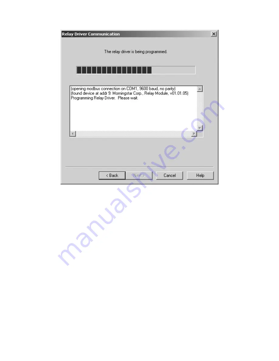
Figure 19. Relay Driver Programming status 


Step 6 

MSView will attempt to communicate with the Relay Driver. If 
there is a problem with the serial connection or 
communications parameters, an error message will appear. 
Check the cable and be sure the correct COM port and 
Address are specified. Also verify that all other programs that 
use the serial port are closed. If the problem persists, try a 
different cable and/or PC. 


When the programming is complete, click 

Finish

 to return to 

the main screen.

  The LEDs on the Relay Driver will flash indicating 

that a power reset is required. Remove power from the Relay Driver 

Summary of Contents for RelayDriver

Page 1: ...RELAYDRIVER TM Logic Module Accessory Installation and Operation Manual Four Channel Relay Driver...

Page 2: ...ion 9 3 1 Open the Setup Wizard 9 3 2 Assign Functions 10 3 3 Programming the Relay Driver 34 4 0 Mounting 40 4 1 Required Tools 40 4 2 Wall Mounting 41 4 3 DIN Rail Mounting 43 5 0 Wiring 45 5 1 Chan...

Page 3: ...tion when performing this task CAUTION Indicates a critical procedure for safe and proper operation of the Relay Driver NOTE Indicates a procedure or function that is important to the safe and proper...

Page 4: ...MORNINGSTAR CORPORATION 1 0 Getting Started 1 1 What s in the Box Relay Driver Software CD Operator s Manual Serial RS 232 Cable 6ft Meter Bus RJ 11 cable 4ft Four 4 Mounting Screws Mounting Template...

Page 5: ...put signals etc DIN Rail Release Tab Snap on Release from DIN rail LED Indicators Displays power and channel status faults sampling interval Meter Bus Ports Connects to other Morningstar products with...

Page 6: ...installation Channel 1 Threshold Function Channel OFF when Vbattery 11 5V Channel ON when Vbattery 12 6V 1 minute delay before turning on off Channel 2 Threshold Function Channel OFF when Vbattery 11...

Page 7: ...p to 1 5MB of available hard disk space Internet connection and service If downloading from web Web browser If downloading from web 2 2 Installing MSView NOTE The software CD provided may not contain...

Page 8: ...time Option 1 Install MSView from the included CD Step 1 Insert the MSView Setup CD in the PC CD drive After a few moments the MSView software setup wizard should appear If setup does not begin or th...

Page 9: ......

Page 10: ...be programmed into the Relay Driver so that it functions as required 3 1 Open the Setup Wizard 1 Click the Windows Start Menu button 2 Under Programs find the MSView Folder 3 Click the Relay Driver Wi...

Page 11: ...Function is assigned as well as a few key parameters Next to each channel Configuration Summary are two setup buttons labeled Simple and Advanced Simple setup allows the user to modify the most essen...

Page 12: ...can be found in sections 3 1 1 to 3 1 6 Choose a Function for each channel s and follow the instructions in the corresponding section For each Function detailed instructions for Simple setup are prov...

Page 13: ...ions Common Applications Unused channel Measure external voltages and signals Setup 1 From the Relay Driver setup screen as shown in Figure 2 choose the Simple setup button next to the desired channel...

Page 14: ...nts the Function switches a channel on or off Additionally delays and minimum maximum timers can alter behavior A variety of control variables may be used including voltage current and temperature val...

Page 15: ...Threshold Function 2 The Channel Function window appears as shown in Figure 3 A list of Functions from which to choose is provided By default the Disabled function is selected Choose the Threshold op...

Page 16: ...cified device on the Meter Bus for variable data such as measured battery voltage load solar voltage and battery temperature The Standalone option uses variable data local to the Relay Driver such as...

Page 17: ...ameters a Select a Control Variable In Figure 5 Battery Voltage has been selected as the Control Variable b Choose a high threshold setpoint c The On Off selection inverses the output when the thresho...

Page 18: ...r instructions on how to program the Relay Driver Threshold Advanced Setup Definitions The following definitions can be used when configuring the Threshold Function in Advanced setup These values are...

Page 19: ...ee Figure 6 Max High Time maximum amount of time the Relay Driver will remain in the High state This timer begins after the Min High timer has expired Min High Time minimum amount of time the Relay Dr...

Page 20: ...larm Fault Function activates a channel in response to a fault or alarm generated by a Morningstar device Any combination of available faults and or alarms from a Morningstar Device can be monitored s...

Page 21: ...the Relay Driver setup screen as shown in section 3 1 choose the Simple setup button next to the desired channel Figure 7 Select the Alarm Fault Function 1 From the list of Functions select the Alarm...

Page 22: ...AR CORPORATION Figure 8 Choose a Control Type 2 The user is prompted to select a Control Type TriStar is selected by default More Morningstar Devices may be added to the list in the future Click Next...

Page 23: ...monitor Four buttons directly below the fault and alarm lists allow the user to check uncheck all items in each list Check each Alarm and Fault that is to be monitored and click Finish NOTE If monitor...

Page 24: ...n be used when configuring the Alarm Fault Function in Advanced setup These values are assigned the appropriate default values in Simple setup Control Address The meter bus ID for the device that is t...

Page 25: ...Refer to the Relay Driver GenStart Supplement for detailed wiring and configuration details The document is available on our website at http www morningstarcorp com products relaydriver WARNING Remote...

Page 26: ...setup screen as shown in section 3 2 choose the Simple setup button next to the desired channel Figure 10 Select GenStart from the function list 2 The Channel Function window provides a list of availa...

Page 27: ...r example if TriStar is chosen the GenStart Function will poll the TriStar over the Meter Bus for data to determine when the generator turns on and off The Standalone option uses local data such as th...

Page 28: ...ents vary between generator models brands Refer to the generator s documentation for required start stop signals Check the box next to each signal that is required to start stop the generator Assign a...

Page 29: ...Choose signal timing parameters 5 Next define the timing for each signal Refer to the generator documentation for recommended durations for each parameter Specify the timing parameters for each signa...

Page 30: ...Function The Control Variable is a list of available variables specific to the Control Type specified in step 3 The Turn On Off thresholds specify the voltage window during which generator charging s...

Page 31: ...hen configuring the Alarm Fault Function in Advanced setup These values are assigned the appropriate default values in Simple setup Control Address the meter bus ID for the device that is to be monito...

Page 32: ...Relay Driver Setup screen choose either Simple or Advanced setup it does not matter which setup type is chosen 2 Select Meter Slave from the Function list Click Finish The channel is now configured f...

Page 33: ...ay Driver variables channel voltages temperature can be read from holding registers via MODBUS Channel voltages can be read from any channel regardless of the control function assigned To control a ch...

Page 34: ...en choose either Simple or Advanced setup 2 Select MODBUS Slave from the Function list Click Finish The channel is now configured for MODBUS Slave If all four channels are configured as desired refer...

Page 35: ...with a PC over a serial cable included Close all programs that may be using the serial port You will not be able to communicate with the Relay Driver over the serial port if the it is already in use b...

Page 36: ...d to a file so that it can be retrieved and referenced at a later date a Click Write to File b Choose a folder on the PC or create one c Type a name for the file d Click Save Figure 16 Connecting the...

Page 37: ...he Relay Driver as shown in Figure 17 The supply voltage should be between 8 68Vdc A DC power supply or small battery will suffice for bench programming The Relay Driver should flash the green LED sta...

Page 38: ...should appear as shown in Figure 18 Select the communications port that is connected to the Relay Driver If you are unsure which port is connected consult the PC user manual The most common ports are...

Page 39: ...sage will appear Check the cable and be sure the correct COM port and Address are specified Also verify that all other programs that use the serial port are closed If the problem persists try a differ...

Page 40: ...STAR CORPORATION for a moment and then reconnect The LEDs should flash the normal start up sequence The Relay Driver is now ready to be installed in the system Section 4 0 explains how to mount the Re...

Page 41: ...RELAY DRIVER 40 4 0 Mounting 4 1 Required Tools Flat blade screw driver Philips screw driver Wire strippers Wire clippers Drill if wall mounting 1 8 drill bit if wall mounting...

Page 42: ...high temperatures corrosive fumes and water Do not install in a confined area where battery gasses can accumulate Step 2 Before starting the installation place the Relay Driver on the surface where it...

Page 43: ...Place the Relay Driver on top of the template to confirm correct positioning With a drill and 1 8 bit drill pilot holes for each of the four mounting screws as indicated on the template Remove the tem...

Page 44: ...not install in a confined area where battery gasses can accumulate Step 2 Place the Relay Driver over the DIN rail in the location where it is to be mounted Make sure there is sufficient room above an...

Page 45: ...have engaged the upper lip of the DIN rail rotate the Relay Driver so that it is flush and parallel to the DIN rail as shown in Figure 22 Step 5 Hold the Relay Driver firmly in position while pushing...

Page 46: ...45 MORNINGSTAR CORPORATION 5 0 Wiring 5 1 Channel Wiring The wiring for each channel is determined by the software configuration This section provides examples of the most common channel wiring...

Page 47: ...22 General channel schematic A general schematic representing each of the four channels is shown above in Figure 23 Each channel has an input resistance of approximately 100k ohms and is diode isolate...

Page 48: ...ground activating the relay coil Multiple relays can be wired to the same channel Each channel can sink a maximum of 750mA of coil current refer to the relay manufacturer s documentation Any type of...

Page 49: ...als as shown in Figure 25 The input voltage source must have the same electrical ground as the Relay Driver ground This type of measurement is commonly referred to as single ended input WARNING Be sur...

Page 50: ...ive a device directly as shown in Figure 26 Possible devices include LED indicators buzzers and small motors The device may be powered by the Relay Driver power source as shown in the figure or from a...

Page 51: ...tary communication protocol to transmit and receive information between each Morningstar Device on the network The Meter Bus ports on the Relay Driver are opto isolated and do not provide power to the...

Page 52: ...51 MORNINGSTAR CORPORATION Meter is also on the network It does not matter which order the devices are connected on the Meter Bus network Figure 26 Example Meter Bus network...

Page 53: ...le 1 Meter Bus loads 5 2 2 Serial Communications Serial communication through the 9 pin RS 232 port on the Relay Module allows the user to program the Relay Driver upgrade the firmware and log data us...

Page 54: ...uence Power LED Green ON Relay Driver is powered and running OFF No power to the Relay Driver Channel LEDs Green ON Channel output is HIGH OFF Channel output is LOW or channel is configured as Input d...

Page 55: ...ault or factory calibration problem Return for service Red Flash Channel LED Only Channel Fault Alarm Indicates a channel short circuit or over current condition Red Flash All LEDs Configuration Updat...

Page 56: ...ll 4 channels 6 3 Maintenance The Relay Driver is designed to run automatically without the need for user intervention However the operator should perform the following tasks annually to ensure contin...

Page 57: ...electronic protections and there are no adjustments or serviceable parts inside Q The Relay Driver and PC are not communicating over the serial port What s wrong A Make sure that the Relay Driver is p...

Page 58: ...work simultaneously Q Are the serial port and Meter Bus ports isolated A Yes Both Meter Bus ports and the serial port are opto isolated Each device on the Meter Bus network can have its own battery or...

Page 59: ...RELAY DRIVER 58 A No Use the Meter Bus for communications between Morningstar Products Note a TriStar must also be connected to the Meter Bus to supply power for communications...

Page 60: ...voltage of channel X Channel Voltage may be used as a control variable even if the channel is not configured as an input TriStar Controller Variables Battery Voltage Reference battery voltage used for...

Page 61: ...if connected to the TriStar Charge and Diversion modes only PWM Duty Cycle Percent of charge current charging the battery at regulation 0 to 100 Bulk Sense Voltage Voltage at the Battery Sense termin...

Page 62: ...harges if the repairs are covered by the warranty WARRANTY EXCLUSIONS AND LIMITATIONS This warranty does not apply under the following conditions Damage by accident negligence abuse or improper use Un...

Page 63: ...20mA Temperature Sensor Range 40 C to 85 C Transient Surge Protection 1500W channel One 9 pin serial RS 232 port opto isolated Two RJ 11 Meter Bus connections in out opto isolated Electronic Protectio...

Page 64: ...1 indoor rated DIN rail attachment 35mm standard Environmental Operating Temperature 40 C to 45 C Storage Temperature 55 C to 85 C Humidity 100 NC Tropicalization conformal coating on both sides of a...

Reviews: