7
ENGLISH
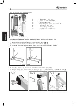
6. Insert the lever for opening the legs and block it with its screw (only for RI701-RI701C-
RI705-RI710-RI710C). (Fig.10)
7. Place the cradle in the corresponding housing, situated at the end of the patient lift arm.
Insert the linchpin and the fixing screw including a nut. (Fig.11)
Fig. 10
Fig. 11a
Fig. 11
8. Put the velcro handles onto the cradle. (Fig.2)
9. The structure is completely assembled (Fig.13). Install the actuator suitable for the chosen
patient lift (Fig.13)
Fig. 12
Fig. 13
Fig. 14
10. ACTUATOR ASSEMBLY ISTRUCTION
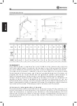
10.1 Assembly HYDRAULIC actuator - RI700C, RI701, RI701C
1. Place the hydraulic actuator as in the picture, blocking well its upper and lower part by
auto-blocking screws and bolts. (Fig.14)
10.2 Assembly TIMOTION electrical KIT (for RI703C, RI705, RI710, RI710C)
1. Secure the support bracket of the control unit to the mast with the provided screws, using
the fitted cavities. (fig.8)
2. Fit the control unit on the bracket, letting it slide from top to bottom and blocking it with
the screws. (Fig.9)
3. Fit the battery into the control unit. (Fig.10)
4. Remove the two actuator mounting bolts from the mast boom. Fit the actuator into it
and secure it with the two bolts previously removed. (Fig.11)
*images for illustrative purpose only


