background image

19 

Settings   


SETTINGS


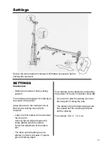
Preparing the calibration test 

 
- Use accurate scales and a container. 
 
- Before carrying out the test, check that   
  no-one is standing near the seed drill      
  except the operator. 
 

Procedure 

 
- Open the trays 

(1) 

and 

(2) 

and push   

  them down and forward in order to lower  
  them below the distribution points. 
 
- Fit the calibration handle 

(3)

 onto the    

  variator shaft. 
 
- Check that the distributions in use are     
   engaged. 


- Perform your calibration test according to  
  the recommendations issued in the           
  following pages.  
 
- To empty the seeds from the tray more  
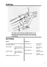
   easily, open the flap slightly lifting the     
   lever 

(4). 


- Raise the trays back into guard position. 


Very precise sowing requires a calibration test. Make sure your scales are accurate. 

Summary of Contents for UNIDRILL 300

Page 1: ...August 2001...

Page 2: ...d that you read this operators manual carefully Please do not hesitate to make suggestions or comments based on your experience they will always be of use to us and will help us improve our products P...

Page 3: ...e I HAVE RECEIVED THE ABOVE MACHINE IN AN ACCEPTABLE CONDITION AND TO THE CORRECT SPECIFICATION I HAVE RECEIVED AND READ THE OWNERS MANUAL FOR SAFE AND CORRECT OPERATION OF MACHINE I WISH TO REGISTER...

Page 4: ...claration of Conformity The Essential Health and Safety Regulations Directive 98 37 EC The Proposed Seed Drills Safety Document 2000 00 714171 DC Design Engineer Date 17 05 2001 DECLARATION OF CONFORM...

Page 5: ...4 Safety Regulations...

Page 6: ...5 Only use Moore Spare Parts The Pressure line of the hydraulic circuit is marked with a red probe cover The Return line of the hydraulic circuit is marked with a blue probe cover...

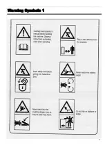
Page 7: ...6 Warning Symbols 1...

Page 8: ...t pins are used when working under raised machine Do not work under raised marker Ensure the tramline system is functioning correctly after each fill Never reach into rotating auger 25 Forward speed s...

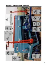
Page 9: ...Safety Instruction Decals 8...

Page 10: ...Safety Instruction Decals 9 25...

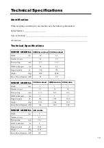
Page 11: ...Width m 2 4 2 4 Number of rows 18 18 Row spacing cm 13 3 13 3 Width in transport m 2 4 2 4 Hopper capacity l 700 700 Weight Kg 2150 2400 Horse Power Required HP 90 90 MOORE UNIDRILL 300 Grassland 300...

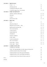
Page 12: ...g the peg wheel variator 18 Preparing calibration test 19 Carrying out calibration test 20 21 Adjusting with the calculator 22 Sowing Depth 23 Coulter height setting tilt setting adjustment 24 Side Ma...

Page 13: ...ly 60 61 Seedbox assembly 62 63 Seedbox drive unit 64 65 Multiplicator 66 67 MS Flow modulation 68 69 Linak Actuator 70 71 Seedbox metering parts 72 73 SPI vertical lift marker 74 75 Electric parts Se...

Page 14: ...bing tight against the discs C SEEDBED PREPARATION It is not necessary to prepare a fine seedbed as for other drills The Uni Drill prepares its own mini seedbed by using an angled disc and seed tube c...

Page 15: ...inkage bar cannot be used in this case Low hitching heights should be preferred such as the pick up hitch or clevis drawbar especially for direct sowing The clevis drawbar is recommended when using du...

Page 16: ...Caution In the three point lifting zone there may be a danger of crushing and sheering 4 Do not stand between the tractor and the machine whilst operating the external lift control lever 5 When in tra...

Page 17: ...drill Insert the locking pins Lower the machine so that it rests on the pins HYDRAULIC CONNECTIONS Double action hydraulic system to lift the seed drill Double action hydraulic system for depth contr...

Page 18: ...seeds Follow the setting instructions 2 Base Flap Move the lever 3 slightly to the right and po sition at the appropriate marker Marker 1 Cereal 1st Wheats only 2 3 4 Peas for canning 5 Peas 6 Beans...

Page 19: ...A Press B Turn 1 Small seeds 8kg ha 2 Large seeds Follow the setting instructions 4 Variator Using the knob 3 and the lever position the marker according to the results of the calibration test 4 Read...

Page 20: ...rder to lower them below the distribution points Fit the calibration handle 3 onto the variator shaft Check that the distributions in use are engaged Perform your calibration test according to the rec...

Page 21: ...Settings 20 Ha 0 m 2 40 3 00 3 50 4 00 4 50 4 80 5 00 6 00 6 66 tr 62 5 50 43 37 5 33 3 31 3 30 25 22 5...

Page 22: ...esponding to the seed drill s width turn steadily at 1 turn per second The number of turns for a 3M drill is 50 The number of turns for a 4M drill is 37 5 See table below 6 Using accurate scales weigh...

Page 23: ...th line 2 which corresponds to the quantity in Kg collected in the trays during the test Without moving the discs on the calculator identify the required sowing rate setting on the Kg ha line 3 Read t...

Page 24: ...ing different combinations of the depth segments NOTE Depth segments are not proportional to machine seeding depth 1 2 3 23 Depth scale The hitching height and drawbar locking position affect the dept...

Page 25: ...ecommended that you raise the coulter approx 40 mm above the disc to improve its mobility Tilt setting adjustment The coulter s cutting edge 1 must be Parallel to the disc As close to the disc as poss...

Page 26: ...ows for infinite horizontal adjustment of the marker arm The discs vertical setting may be altered in order to increase or reduce ground marking depth Four settings can be applied by alternating the p...

Page 27: ...S Safety The marker safety devices only operate in the working position Active Safety Flexible tine buffer between the arm and disc Passive Safety M8 x 40 class 6 8 safety shearing bolt 1 Replacement...

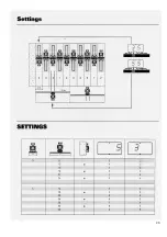
Page 28: ...tware reference UDJ 308 SETTINGS Tramlining system Principle Its purpose is to create tramlines with a view to future treatments using machines whose width is a multiple of the seed drills working wid...

Page 29: ...28...

Page 30: ...raising the seed drills in mid field for instance does not alter tramlining settings To operate the unit please refer to the MOORE TRONIC operator s manual Pull the hydraulic spool lever to reverse th...

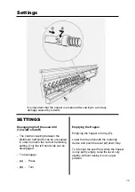
Page 31: ...nd side can be disengaged To disengage a Press b Turn Emptying the Hopper Emptying the hopper into tray 1 Lower the trays beneath the metering device and push the lever 2 down fully To interrupt the s...

Page 32: ...or seed germination It is recommended that the centre of the field should be drilled first and the headlands last If the headlands are planted first then the tractor and drill will travel and turn on...

Page 33: ...to the soil underneath being too loose The drill will cut cleanly through given that it has something to bite on Consolidating the field with either rollers or a land packer sufficient to allow the d...

Page 34: ...leather jackets Slug pellets should be used as required H PREVENTING SOIL COMPACTION 1 Whenever possible use low pressure tyres on all machines operated in fields in order to reduce superficial compa...

Page 35: ...works exclusively in the sowing line which avoids seeds that escaped the stale seed bed from emerging Prefer wide spacing between rows such as that of the UNIDRILL 16 6 cm 6 Watch for the evolution o...

Page 36: ...easily followed for pre emergence chemical applications This is achieved by activating the float position on the spool valve whilst on the tramline bout ii Pre loading Dragarms If it is noticed that d...

Page 37: ...o firms specialising in their disposal 6 Before undertaking any electrical work on the tractor or attached machine disconnect the alternator cable and the battery 7 Protective covers which are prone t...

Page 38: ...after Lubricate the tramline clutch springs by spraying with penetrating oil Lubricate the drive chains Check the oil level in the variator with the seed drill horizontal and top up to the red dot wit...

Page 39: ...rly when using the seed drill on hard or rocky soil The disc coulter tip should be running parallel with the disc so that they are just touching This will reduce the build up of trash between the disc...

Page 40: ...the following parts After 20 hours of use Check the tightness of the main bolts 2 1 After 10 hours of use Check the tightness of the disc mounting bolts disc fastening screws and the tapered hub beari...

Page 41: ...Maintenance Tyre pressure chart for 10 0 75 15 3 Vredestein Tyres 40...

Page 42: ...Optional Equipment Section 5 MS Flow Modulation 41...

Page 43: ...atory to connect the 2 Power supply circuit with 7 5 Amp fuse Unit directly to the 12 Volt 3 Sower Ram Bundle battery with the connection cable provided The unit should be lit up when the connection i...

Page 44: ...Starting up 43...

Page 45: ...Starting up 44...

Page 46: ...Operation 45...

Page 47: ...Operation 46...

Page 48: ...Operation 47...

Page 49: ...Operation 48...

Page 50: ...Operation 49...

Page 51: ...50 D E...

Page 52: ...e lever in the tractor cab The rear axle cylinders will extend retract when the appropriate spool valve has been operated in the tractor When the button is pressed and held down on the joystick and th...

Page 53: ...switch joystick The recess in both plates allows a close fit for the spool lever Plates held together by 4 3 16 x 1 1 2 screws Trigger Switch Joystick Mounting Bracket Part No ED 04 Joystick Mounted t...

Page 54: ..._________________________ _____________________________ _____________________________ _____________________________ _____________________________ _____________________________ ________________________...

Page 55: ...Dragarm Seeding Unit 47 48 54 Parts list...

Page 56: ...m Tungsten 31 A139 M10 Locknut 207 1234LTG Seed Tube Coulter R H 30mm Tungsten Grass 33 A146 M16 X 34 H D Washer 8 208 1234L Seed Tube Coulter L H 30mm 34 A148 3 8 Spring Washer 208 1234LT Seed Tube C...

Page 57: ...e Axle and Super Scrapper Complete Assembly Part No 201 40N Arable Drill Stepped Axle Unit Part No 1 4A Arable Drills 3 2 4 4 1 2 3 1 5 6 7 9 8 Bogie Axle Parts 56 Parts list Arable Drill Stepped axle...

Page 58: ...Scraper Mounting Bolt M12 X 30 Cup Square 4 A138 Nut M12 Nyloc A138 Nut M12 Nyloc 5 1 303A Bogie Long Arm 6 201 4E Bogie Spacer 7 A151 Unipack Bearing 30mm 8 201 43 Bogie Mount 9 201 42N Bogie Short...

Page 59: ...Drawbar and Rear Axle Assembly 58 Parts list 47 48 45 1 2 49 3 4 50 51 52 53 53 A B 55 54 35...

Page 60: ...X 8 Drawbar Pin 8 129 1234 Ram Bottom Pin 49 120 8A Drawbar mounting pin 9 130 1234 Pivot Collar Axle Unit 50 2 9A Drawbar 300 Arable 10 131 1234 Pivot Bush Axle Unit 2 9AG Drawbar 300 Grassland 21 A1...

Page 61: ...Drive wheel Assembly 60 Parts list 26...

Page 62: ...10 A111 M12 X 55 Bolt 11 A214 M10 X 80 Bolt 12 A121 M10 X 40 Setscrew 13 A132 3 4 UNF Locknut 14 A138 M12 Locknut 15 A145 M20 X 34 Heavy Duty Washer 16 A156 3 8 Timken Tapered Roller Bearing 17 A157N...

Page 63: ...Seed Box Assembly S900520 S901537 62 Parts list...

Page 64: ...Clutch Spring 32 S901546 Seed Box End Bearing 63 S901538 Fine Seed Clutch Wheel 33 S900952 Agitator Bearing Plate 64 S901539 Standard Seed Wheel 34 S908010 Retention Spring 65 S901542 Seed Wheel Lock...

Page 65: ...Seed Box Drive Unit 64 Parts list...

Page 66: ...84008 Oil Drain Plug 10 S590306 Roll Pin 6 X 30 35 S737003 Oil Drain Seal 11 S596875 6 X 56 Key 36 S712014 Freewheel Collar 12 S922033 Drive Shaft 37 S914025 Variator Cover 13 S987703 Gasket 38 S59010...

Page 67: ...Multiplicator Parts list 66...

Page 68: ...lip 3 S711015 Bearing 30 x 47 x 9 4 S980781 Sprocket 35 Tooth 5 S980780 Sprocket 25 Tooth 6 S930024 Sprocket Bar 7 S915041 Multi Sprocket 25 Tooth 8 S590407 Roll Pin M8 x 35 9 S590207 Roll Pin M5 x 35...

Page 69: ...MS Flow Modulation Parts list 1 3 2 7 10 8 9 11 6 5 4 15 14 12 13 68...

Page 70: ...5 MS 05 Linak actuator mounting bracket 6 MS 06 Mounting bracket setscrews M8 x 20 7 MS 07 M8 Washer 8 MS 08 Linak actuator 9 MS 09 Linak actuator top bolt M10 x 100 10 MS 10 Linak actuator bottom bol...

Page 71: ...Linak Actuator Tramline Mechanism Parts list 1 5 2 7 6 4 3 9 8 70...

Page 72: ...ator cable 3 LA 03 Linak Arm Support 4 A219 Arm support mounting bolts M8 x 20 A140 M8 Nyloc nut 5 A218 Linak Actuator Arm support bolt M8 x 35 A140 M8 Nyloc nut 6 A218 Linak Actuator Adjustable stop...

Page 73: ...Seedbox Metering Parts Parts list 10 12 11 8 6 5 4 3 9 2 1 7 72...

Page 74: ...rap Spring 3 S901539 Standard Seed Wheel S901538 Fine Seed Wheel 4 S985209 Skid Flap 5 S525895 M8 X 45 Screw 6 S571806 M8 Nut 7 S909081 Skid Flap Spring 8 S904599 Skid Flap Support 9 S985210 Rape Shut...

Page 75: ...SPI Vertical Lift Marker 74 Parts list...

Page 76: ...ot Nut M16 12 S921017 Marker Disc Shaft 35 S962071 Locking Plate 13 S908360 Bearing Holder 36 S920019 Lateral Pivot 14 S711000 Marker Bearing 37 S732005 Washer 15 S415717 Marker Bearing End Cap 38 S57...

Page 77: ...Moore Vertical Lift Marker 17 13 16 47 48 Complete disc hub assembly 14 15 74 Parts list...

Page 78: ...S590407 Spirol Pin M8 X 35 20 S571366 Nut M16 X 7 40 S719001 Grease Nipple M8 S571216 Nut M16 X 15 41 S910395B Marker Mounting Bracket Left 21 S571216 Nut M16 X 15 41B S910395 Marker Mounting Bracket...

Page 79: ...Electric Parts Sensors Parts list 1 4 3 2 76...

Page 80: ...ectric Parts Sensors Parts list Item Part No Description 1 S983917 Low level hopper sensor 2 S983912DS Distribution shaft sensor 3 S983912AS Agitator Shaft Speed area sensor 4 S983912M Marker sensor 7...

Page 81: ...Electric Parts Chassis Parts list 17 18 16 19 27 11 9 8 10 12 14 15 13 3 1 2 7 4 6 5 24 25 20 21 22 23 26 78...

Page 82: ...100 11 MS 11 M10 Washer 12 MS 12 MS pod mounting bracket 13 MS 13 Ms pod mounting bracket setscrews M6 x 20 14 MS 14 Mounting bracket clamp 15 MS 15 Mounting bracket clamp setscrews M8 x 35 16 MT 01...

Page 83: ...84 85 80 Calibration Charts Section 7 CALIBRATION CHARTS Calibration Charts The calibration charts are only stated for information purposes only Check your spreading rate per hectare for greater prec...

Page 84: ...Calibration Charts Table 1 Recommended Shutter Base flap and Peg wheel Positions Shutter Opening Base Flap Position Peg wheel selection 81...

Page 85: ...28 30 32 34 90 180 27 29 32 34 36 39 100 200 30 33 35 38 40 43 110 220 33 36 39 42 44 47 120 240 36 39 42 45 48 51 130 260 39 43 46 49 52 54 140 280 42 46 49 52 55 58 150 300 45 49 52 55 58 61 160 32...

Page 86: ...Calibration Charts Calibration charts for Rape Barley Peas and Field Beans 83...

Page 87: ...Calibration Charts Calibration charts for Oats Mustard Phacelia and Radish 84...

Page 88: ...Calibration Charts Calibration charts for Lucern Linseed Rye grass and Clover 85...

Page 89: ...Notes 86...

Page 90: ...hin 12 months from the date of receipt by the purchaser or his her nominee of the machine 5 Any claim under this warranty must be made by the original purchaser of the machine and is not assignable to...

Page 91: ...e Therefore MOORE UNIDRILL Ltd will not accept responsibility for any discrepancies which may occur between the specification of machines thereof contained in this publication MOORE UNIDRILL LTD 33 KI...

Reviews: