Settings
E : Markers
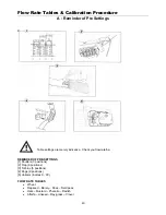
Setting Markers to working position
Markers are designed for marking the tractor centerline.
Markers are pre –adjusted in the factory, but they need to be checked in the field, if adjustment is required
move the disc bracket (A) along the tube. This can be done by slackening the U bolt (2)
The distance between the first sowing row and the marker disc equals ½ sowing width plus ½ the seed row
spacing.
The disc angle can be changed by loosening bolt (1) and increasing the disc angle to get the desired
marking intensity.
Operation of markers using Moore headland Control
See page 46 for operation of markers on the Moore Headland control
The markers should be operated in a gentle manner, beware of obstacles when
drilling, turning at the headlands should be carried out with the markers in the
home position
A
29
Summary of Contents for Tandem Uni-Drill DP400A
Page 9: ...Safety Regulations Safety Stickers 9 ...
Page 17: ...Start Up G TURBINE 17 ...
Page 23: ...Settings A Distribution Settings 23 ...
Page 32: ...Settings H Tramline Track Width 32 ...
Page 41: ...Flow Rate Tables Calibration Procedure 41 ...
Page 42: ...Flow Rate Tables Calibration Procedure 42 ...
Page 43: ...Flow Rate Tables Calibration Procedure 43 ...
Page 44: ...Flow Rate Tables Calibration Procedure 44 ...
Page 45: ...Flow Rate Tables Calibration Procedure 45 ...
Page 48: ...DP400A and DP600A Parts booklet 2002 seeding line ...
Page 52: ...2002 DP600A markers ...
Page 54: ...Marker Circuit Diagram ...
Page 55: ...W Seed box hopper extension ...
Page 56: ...W Seed box Peg Wheels ...
Page 57: ...W Seed box Distributor Assembly ...
Page 58: ...W Seed box Distributor Assembly ...
Page 59: ...W Seed box Variator Assembly W Seed box Variator Assembly ...
Page 60: ...W Seed box half width shut off ...
Page 61: ...W Seed box Venturi System ...
Page 62: ...W Seed box Drive Wheel Assy ...
Page 63: ...W Seed box Wind turbine Assy ...
Page 64: ...W Seed box Air Intake ...
Page 65: ...W Seed box RDS system ...

