RS03/06-S/Q Hardware Manual
RS03/06-S/Q Hardware Manual
23
9 / 28 / 2015
+86-400-820-9661
3.4.1 Digital Inputs
3.4.1.1 X1/STEP/CW Limit and X2/DIR/CCW Limit High Speed Digital Inputs
X1/STEP and X2/DIR are high-speed digital inputs operation 5-24V optical isolated differential
signal, minimum pulse width 250ns, maximum pulse frequency 2MHz.
•
In Pulse and Direction mode, X1/STEP is pulse input and X2/DIR is direction signal input.
•
In CW/CCW mode, X1/STEP is CW pulse input and X2/DIR is CCW pulse input.
•
In A/B quadrature mode (Encoder following), X1/STEP is signal A input, X2/DIR is signal B
input.
•
In velocity mode, X1/STEP can be set to RUN/STOP, X2/DIR is direction signal. X1 and X2
also can be con
fi
gured as CW JOG and CCW JOG.
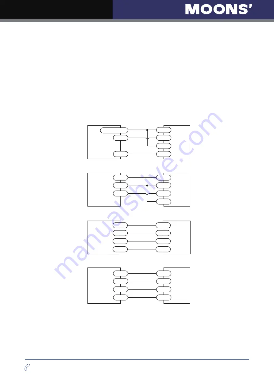
The diagrams below show how to connect the X1/STEP and X2/DIR to various commonly used
Connecting to Host with Sinking Outputs
+5v - +24v out
DIR
STEP
DIR+
DIR-
STEP+
STEP-
Host with
Sinking Outputs
RS-S/Q
Connecting to Host with Sourcing Outputs
DIR
COM
STEP
Host with
Sourcing
Outputs
DIR+
DIR-
STEP+
STEP-
RS-S/Q
Connecting to Host with Differential outputs
DIR+
DIR-
STEP+
DIR+
DIR-
STEP+
STEP-
STEP-
Host with
Differential
Outputs
RS-S/Q
Connecting to An Encoder
A+
A-
B+
STEP+
STEP-
DIR+
DIR-
B-
Encoder
RS-S/Q


