


- 2 -
CAMERA BRACKET SETUP
8.
To adjust the camera bracket, loosen the two thumb screws
(Figure 6). When the desired focus and location are achieved
tighten the thumb screws on the brackets in place using needle
nose pliers. Use Loctite™ or equivalent to secure the screws,
especially in installations where vibration is a concern.
Figure 3
1. Connect the output of your Class 2 Power Supply to the terminal
connectors on the PC Board inside the housing. Refer to the
Troubleshooting section later in this instruction sheet for more
information.
2.
Connect the incoming video cable to the BNC connector.
NOTE:
For NVT Twisted Pair see Addendum 1.
Terminal Connector
Positive
Negative
NOTE:
The following instructions are for camera bracket setup,
camera focusing, and camera set-up.
The final steps for installation follow these sections.
Use Class 2 Power only. Input voltage must be
between 12-28 VDC or 15-28 VAC.
WIRING (Figure 3)
Connected to
the Camera
Connect to
incoming video
BNC
Power
Board
DESCRIPTION
The Warrior Test Monitor Cable is a tool that allows users to
view video from cameras via a small on-site monitor. It's quick
and easy to use.
1.
Using the security tool provided, loosen the four security
fasteners and remove the housing top.
NOTE:
The housing
top is held to the base by a lanyard.
2. Locate the power board on the inside of the housing. The Test
Monitor Cable plug is located beside the terminal block where
incoming power is connected (Figure 4).
Figure 4
Power Board
Terminal Connector
Test Monitor Cable plug
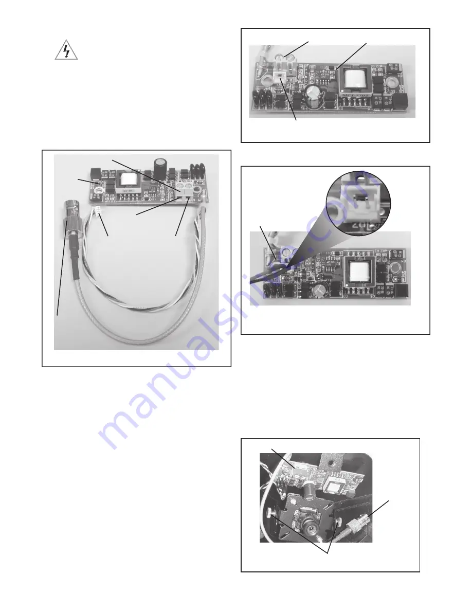
3.
Plug the test monitor cable into the power board (Figure 5).
Attach the BNC connector to your test monitor.
Test Monitor Cable (NOTE: Your cable may look different)
Figure 5
The plug for the Test
Monitor Cable is polarity
protected and can only
be inserted one way.
OPTIONAL WARRIOR TEST MONITOR CABLE
(Part # - WSTMC)
Terminal Connector
Video
Connector
Figure 6
Bracket adjustment thumb screws


