


- 6 -
Factory Settings
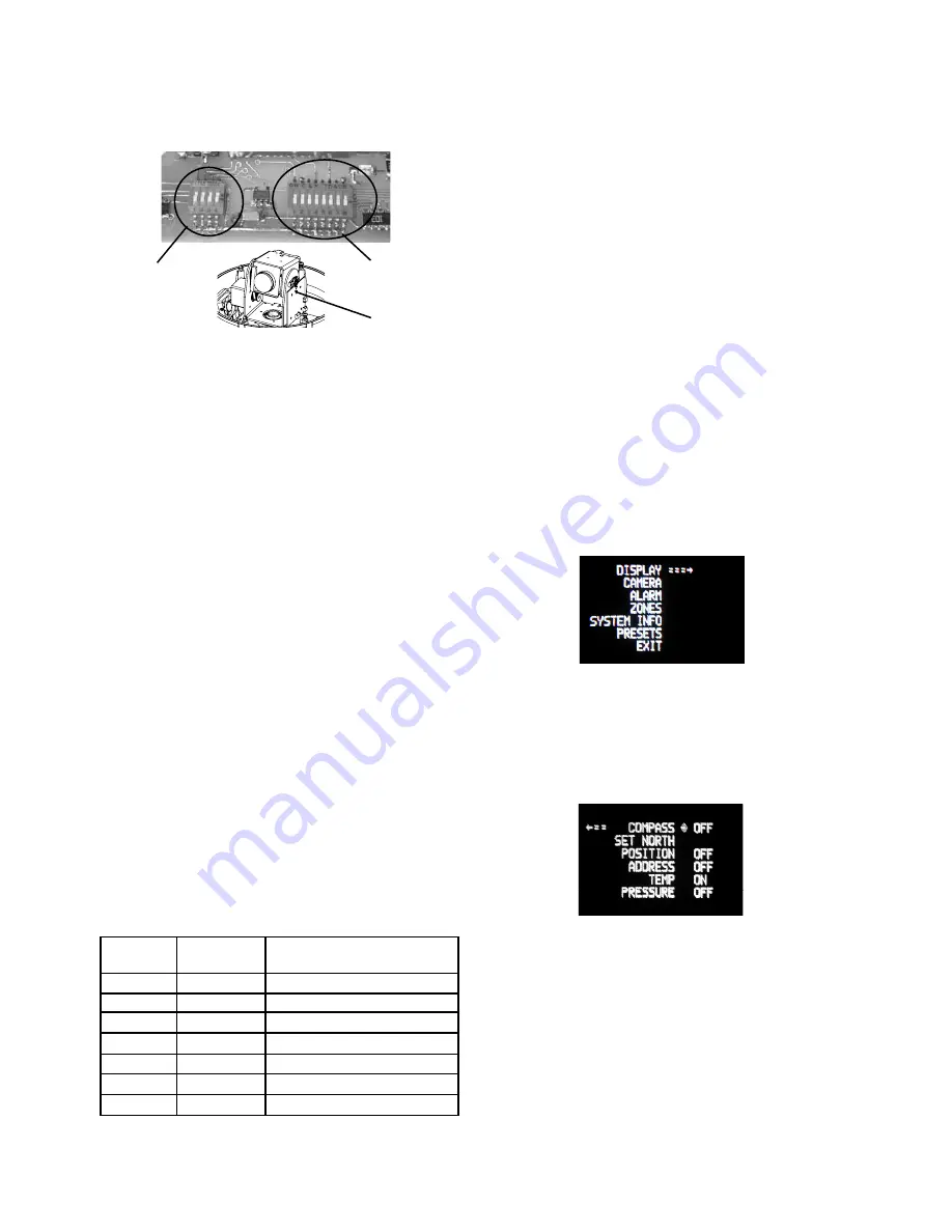
DO NOT ADJUST
PC Board
located here
SETTING THE ADDRESS FOR THE UNIT
Each pan/tilt must have its own unique address. The factory
default address is 001
. To change this address use the 8 position
dip switch located on the PC Board on the side of the pan/tilt (Figure
4), referring to the chart in the back of this manual. The address is
set with the rocker style dip switches, which are non-volatile. The
address cannot be changed unless the dip switches are moved, or
unless the Remote Address feature in the VLC485 software is used.
Address
Dip Switches
SETTING PROTOCOL FOR THE UNIT
There are no user settings for protocol selection. The MR7CS-9™ will
respond to Pelco D, Pelco P, or Videolarm VL422 protocol automati-
cally (1 start bit, 1 stop bit, 8 data bits, no parity).
MENU DRIVEN SETTINGS
To enter the Main Menu, go to preset 95. The picture will disappear and
the menu selections will appear on screen.
When you are in the Main Menu pan and tilt functions will not control
the motion of the pan/tilt (except where noted). Instead, “Tilt Up” or
“Tilt Down” will be used to navigate up or down along the main menu.
"Pan Right” and “Pan Left” will be used to select between the main
menu selection and the sub menu. The “Zoom In” and “Zoom Out”
are used to turn the selected functions on or off.
DISPLAY -
This controls the display of the compass heading and
allows the user to calibrate the compass heading. PAN RIGHT to
access the sub-menu. TILT DOWN to access each item. PAN LEFT
to return to the main menu.
OPTIONAL SETTINGS FOR THE MR7CS-9™
Protocols
The MR7CS-9™ supports VL422, Pelco P, and Pelco D protocols. The protocol
is sensed automatically so there are no dip switches or adjustments for
setting the protocol.
Day/Night Camera
When the light level is low, the camera will switch out the infrared filter and
go to black and white mode. This feature can be permanently turned off, on,
or set to automatic mode by using the menu in the On Screen Display.
Zones
There are 16 zones that may be programmed in the MR7CS-9™. Each zone
may be set as a privacy zone with the video off. The zone title, if programmed
and enabled, will be displayed regardless of whether the zone is programmed
for privacy or not.
Presets
The MR7CS-9™ has 64 presets that can be used individually or as part of
an auto tour. Preset 1 is the “home preset”; In addition, some presets have
special functions as shown in the table below:
PRESET
NUMBER COMMAND FUNCTION
66 GO TO Show this table
70 GO TO Start Auto Tour
80 GO TO Run Pattern
80 SET Start Recording Pattern
81 SET Stop Recording Pattern
89 GO TO Put Camera Into Auto Iris Mode
95 GO TO Display Main Menu
Auto Tour
The auto tour function will automatically go, in sequence, to each preset
that has been programmed. The dwell time for each preset can be set indi-
vidually to be from 0 to 99 seconds.
NOTE: When the dwell time is set to "0" the preset will be replaced by
the pattern (see below for setting). The pattern will execute,
then auto tour will resume. More than one preset may be
replaced by the pattern.
Pattern
A pattern is a programmed continuous path. The camera will follow this
path repeatedly until the pattern is stopped. One pattern, with a maxi-
mum pattern time of 128 seconds, can be set.
COMPASS
- The display show “COMPASS ON” or “COMPASS
OFF”. Press “zoom in” to turn the compass heading on and “zoom
out’ to turn the compass display off.
SET NORTH
- Press “zoom in” button to set calibration. The
display will show “OK”.
POSITION
- This displays the pan and tilt positions of the camera.
Press "zoom in" to turn this on, "zoom out" to turn it off.
ADDRESS
- This displays the camera address. Press "zoom in" to
turn this on, "zoom out" to turn it off.


