background image

PVVEX58-300 & PVVEX510-300 Horizontal Power Vent

Page 19

XG0518 - 070714

Appendix

Appendix B: State of Massachusetts

Amendment

 (Gas Fireplace / Equipment sold in the State of Massachusetts)

 5.08: Modifications to NFPA-54, Chapter 10


(1) Revise NFPA-54 section 10.5.4.2


by adding a second exception as follows:

Existing chimneys shall be permitted to have their use continued when a gas conversion burner is installed, and shall be equipped with a manually reset device 

that will automatically shut off the gas to the burner in the event of a sustained back-draft

.


(2) Revise 10.8.3

 by 

adding the following additional requirements:

(a) For all side wall horizontally vented gas fueled equipment installed in every dwelling, building or structure used in whole or in part for residential purposes, 

including those owned or operated by the Commonwealth and where the side wall exhaust vent termination is less than seven (7) feet above finished grade in 

the area of the venting, including but not limited to decks and porches, the following requirements shall be satisfied: 


1. INSTALLATION OF CARBON MONOXIDE DETECTORS.


At the time of installation of the side wall horizontal vented gas fueled equip-

ment, the installing plumber or gas fitter shall observe that a hard wired carbon monoxide detector with an alarm and battery back-up is installed on the floor 

level where the gas equipment is to be installed. In addition, the installing plumber or gas fitter shall observe that a battery operated or hard wired carbon 

monoxide detector with an alarm is installed on each additional level of the dwelling, building or structure served by the side wall horizontal vented gas fueled 

equipment. It shall be the responsibility of the property owner to secure the services of qualified licensed professionals for the installation of hard wired carbon 

monoxide detectors

a. In the event that the side wall horizontally vented gas fueled equipment is installed in a crawl space or an attic, the hard wired carbon monoxide detector with 

alarm and battery back-up may be installed on the next adjacent floor level.

b. In the event that the requirements of this subdivision can not be met at the time of completion of installation, the owner shall have a period of thirty (30) days 

to comply with the above requirements; provided, however, that during said thirty (30) day period, a battery operated carbon monoxide detector with an alarm 

shall be installed.


2. APPROVED CARBON MONOXIDE DETECTORS.


Each carbon monoxide detector as required in accordance with the above provisions 

shall comply with NFPA 720 and be ANSI/UL 2034 listed and IAS certified. 


3. SIGNAGE.


A metal or plastic identification plate shall be permanently mounted to the exterior of the building at a minimum height of eight (8) feet 

above grade directly in line with the exhaust vent terminal for the horizontally vented gas fueled heating appliance or equipment. The sign shall read, in print 

size no less than one-half (1/2) inch in size, “GAS VENT DIRECTLY BELOW. KEEP CLEAR OF ALL OBSTRUCTIONS”.


4. INSPECTION.

 The state or local gas inspector of the side wall horizontally vented gas fueled equipment shall not approve the installation unless, 

upon inspection, the inspector observes carbon monoxide detectors and signage installed in accordance with the provisions of 248 CMR 5.08(2)(a)1 through 4. 

(b) EXEMPTIONS: The following equipment is exempt from 248 CMR 5.08(2)(a)1 through 4: 


1. The equipment listed in Chapter 10 entitled “Equipment Not Required To Be Vented” in the most current edition of NFPA 54 as adopted by the 

Board; and 


2. Product Approved side wall horizontally vented gas fueled equipment installed in a room or structure separate from the dwelling, building or struc-

ture used in whole or in part for residential purposes.  


(c) MANUFACTURER REQUIREMENTS - GAS EQUIPMENT VENTING SYSTEM PROVIDED

. When the manufacturer of Product 

Approved side wall horizontally vented gas equipment provides a venting system design or venting system components with the equipment, the instructions 

provided by the manufacturer for installation of the equipment and the venting system shall include:


1. Detailed instructions for the installation of the venting system design or the venting system components; and


2. A complete parts list for the venting system design or venting system. 


(d) MANUFACTURER REQUIREMENTS - GAS EQUIPMENT VENTING SYSTEM NOT PROVIDED

. When the manufacturer of a Prod-

uct Approved side wall horizontally vented gas fueled equipment does not provide the parts for venting the flue gases, but identifies “special venting systems”, 

the following requirements shall be satisfied by the manufacturer:


1. The referenced “special venting system” instructions shall be included with the appliance or equipment installation instructions; and 


2. The “special venting systems”

 shall be Product Approved by the Board, and the instructions for that system shall include a parts list and 

detailed installation instructions. 

(e) A copy of all installation instructions for all Product Approved side wall horizontally vented gas fueled equipment, all venting instructions, all parts lists for 

venting instructions, and/or all venting design instructions shall remain with the appliance or equipment at the completion of the installation.


(3) After NFPA-54 section 10.10.4.2

 add a new section 10.10.4.3 as follows:

When more than four gas appliances are to be vented through a common gas vent or common horizontal vent manifold, a plan of the proposed vent installation 

shall be submitted to the Inspector and the serving gas supplier for review and approval.

Extraction from: Massachusetts Rules and Regulations

5.00: Amendments To 2002 Edition Of ANSI Z223.1-NFPA-54

Summary of Contents for PVVEX510-300

Page 1: ...plosion risk Oxidising Danger of death Biohazard Laser Radiation Danger of entrapment Hot surface General Warning Blank Gas bottles Watch for falling objects Electricity Danger for cutter Entrapment hazard Battery hazard Rotating parts Low temperature Strong magnetic field Optical radiation Non ionizing radiation Radiation Hazardous to the Environment Danger of harming your hands Irritant Cutting ...

Page 2: ...arness EPVH20 20 foot power cord and harness EPVH30 30 foot power cord and harness EPVH40 40 foot power cord and harness EPVH50 50 foot power cord and harness EPVH60 60 foot power cord and harness EPVH70 70 foot power cord and harness EPVH80 80 foot power cord and harness EPVH90 90 foot power cord and harness EPVH100 100 foot power cord and harness Specifications Before Your Begin For vent configu...

Page 3: ...4 610 PVVEX58 300 Vertical Po 8 3 8 66 4 10 17 432 17 432 5 126 8 202 ical Power Vent Termination 18 3 8 466 10 1 2 267 6 7 8 174 16 1 2 419 24 610 17 432 17 432 126 PVVEX58 300 PVVEX510 300 Horizontal Power Vent 18 3 8 466 16 1 2 419 24 610 24 610 5 126 8 202 PVVEX58 300 Vertical Power Vent Termination Bottom View Introduction Page 3 XG0518 070714 ...

Page 4: ...orizontal Power Vent Page 4 XG0518 070714 16 1 2 419 18 3 8 466 6 7 8 175 13 330 24 610 24 610 18 458 18 458 5 126 10 253 PVVEX510 300 Vertical Power Vent Termination Figure 1a PVVEX58 300 PVVEX510 300 Tolerance mm Installation ...

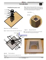
Page 5: ...m municate with the Power Vent Run vent pipe from the fireplace to the chase Make sure the last section is female end up and is flush with the top of the chase without going above it See figure 2b Figure 2b Installing the Rough in Kit Figure 2c Installing the Rough in Kit 20 Max 20 Max PVVEX58 300 10 5 8 270 Min 10 5 8 270 Min 24 Min PVVEX510 300 13 330 Note Follow local and or national code requi...

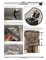
Page 6: ...ews securing strain relief plate and remove it Strain Relief Plate Figure 2g Step 6 Loosen nut on the strain relief of the control cable Pass control cable through slot in rough in box making sure the nut stays is on the opposite side of the rough in box as the strain relief Figure 2h Step 7 Push the strain relief through the hole in the roughin box Figure 2i Step 8 Reinstall the strain relief pla...

Page 7: ...the electrical harness EPVH 10 100 that will communicate with the Power Vent module Step 3 Install the power vent Rought in Kit Remove the electrical cover plate from inside of the rough in kit Pull the control cable through the slot in the bottom of the box and insert the plug into the rectangular hole in the cover plate Re attach the cover plate Pull wire harness throught the supplied hole in th...

Page 8: ...of water or moisture Attachment screw locations Attachment screw locations Step 16 Place power vent over chase and fasten with 4 screws on the vertical sides of the base plate Silicone of seal the base plate in any location necessary to keep the structure of the building free of water or moisture Conduit Wiring clearances Connect the power vent harness as outlined Connect the wiring to the firepla...

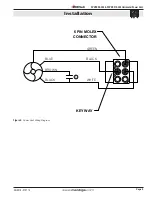
Page 9: ...PVVEX58 300 PVVEX510 300 Horizontal Power Vent Page 9 XG0518 070714 Figure 4 Power Vent Wiring Diagram C Power Vent Wiring BLUE BROWN BLACK WHITE BLACK GREEN 6 PIN MOLEX CONNECTOR KEY WAY Installation ...

Page 10: ...inches 30 inches I clearance to inside corner 30 inches 30 inches J clearance to each side of the vertical centerline of a metre or regulatory assembly to a maximum vertical distance of 15ft 3 feet 3 feet K clearance to service regulator vent outlet 3 feet 3 feet L clearance to non mechanical air supply inlet to the building or combustion air inlet to other appliance for appliance 100 000 BTU H 30...

Page 11: ...the 4 outer screws that fasten the top cover to the termination Remove the cover Figure 5 Capacitor Replacement REC1252 Turn off power and gas before servicing Figure 5a Step 2 Cut zap straps Step 3 Unscrew ground wire capacitor bracket from motor WARNING Save this screw Figure 5b Step 4 Cut brown wire from motor and black wire from capacitor Figure 5c Step 5 Cut black fibre wire from power cable ...

Page 12: ...citor and ground wire to the motor using the existing screw you saved Figure 5g Step 9 Using a small bell connector connect the blue wire from the motor to the black fibre wire from the power cable Figure 5h Step 10 Using the large bell connector attach the white fibre wire from the power cable to the black wire from the motor and a black wire from the capacitor Figure 5i Step 11 Using the other s...

Page 13: ...y or not at all it is wired incorrectly Put the top cover back on using the supplied replacement screws Top Cover Top Cover Screws x 4 plcs Screw Locations x 4 plcs Wind Baffle Rain Skirt Screw Locations x 5 plcs Top Separator Step 1 a Remove the 4 outer screws that fasten the Top Cover to the termination b Remove the Cover PVVEX58 300 Motor Removal Servicing Step 2 a Remove the 4 outer screws tha...

Page 14: ...nd baffle to the termination Lower the wind baffle to rest on the rain skirt Top Cover Top Cover Screws x 4 plcs Screw Locations x 4 plcs Wind Baffle Rain Skirt Screw Locations x 5 plcs Top Separator s ng s to s or r Figure 6a Step 3 Remove the 5 outer screws that fasten the top separator to the termination Remove the top separator Top Cover Top Cover Screws x 4 plcs Screw Locations x 4 plcs Wind ...

Page 15: ...otor mounting plate Figure 6g Figure 6h Step 9 Lift out motor and capacitor REC1253 Figure 6i Step 10 Drop new motor assembly into the power vent and screw with supplied 4 screws and star washers Line up cut out in motor mounting plate with electrical conduit Figure 6j Step 11 Remove the ground wire screw from the motor NOTE Save this screw for later Figure 6k Service ...

Page 16: ...black wire from the motor and one of the black wires from the capacitor Figure 6m Step 14 Using a small bell connector connect the black fibre wire from the power cable to the blue wire of the motor Figure 6n Step 15 Using the other small bell connector connect the other black wire from the capacitor to the brown wire from the motor Figure 6o Step 16 Using a zap strap to bundle the wires neatly to...

Page 17: ... Step 21 Test the power vent and make sure it is working properly When looking down at the top of the motor the fan should be spinning counterclockwise If it is spinning the wrong way or not at all it is wired incorrectly Put the top cover back on using the supplied replacement screws Top Cover Top Cover Screws x 4 plcs Screw Locations x 4 plcs Wind Baffle Rain Skirt Screw Locations x 5 plcs Top S...

Page 18: ...by The Companies 2 The Montigo Gas Appliance must be subjected to normal use The Gas Appliances are designed to burn gas only Burning conventional fireplace fuels such as wood coal or any other solid fuel will cause damage to the Gas Appliance will produce excessive temperatures and will result in a fire hazard Limitations On Liability It is expressly agreed and understood that The Companies sole ...

Page 19: ...imum height of eight 8 feet above grade directly in line with the exhaust vent terminal for the horizontally vented gas fueled heating appliance or equipment The sign shall read in print size no less than one half 1 2 inch in size GAS VENT DIRECTLY BELOW KEEP CLEAR OF ALL OBSTRUCTIONS 4 INSPECTION The state or local gas inspector of the side wall horizontally vented gas fueled equipment shall not ...

Page 20: ...Ferndale Washington TF 1 800 789 6236 FX 1 866 3000 0927 XG0518 070714 Langley British Columbia TF 1 800 378 3115 FX 1 604 607 6462 PVVEX58 300 PV VEX510 300 Power Vent Termination ...

Reviews: