14
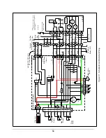
Relay K2
- is controlled by the Magnetic Bond Switch S3. The output contacts of K2 are
connected to the red/green, red/yellow and red/black wires in the interconnecting cable. These
outputs are intended for use with an external device such as an automatic door opener.
Electromagnet
– The electromagnet operates on a nominal 24Vdc and draws approximately 300
mA when energized. Diode D8 is across the magnet terminals to suppress voltage spikes that can
be generated when the magnet de-energizes.
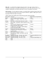
Table 2, Status of the Signals on the interconnecting cable in the Secure Mode.
Wire Color
Function
Signal status in Secure Mode
Brown
Common reference for all signals
0 Vdc
Red
Fixed +24 Vdc supply voltage from control
module
+24 Vdc
Orange
Red lamp, controlled by internal door switch
0 Vdc
Yellow
Green lamp, controlled by internal magnetic bond
switch
0 Vdc
Green
Yellow lamp, controlled by internal magnetic
bond switch and control module
+24 Vdc
Blue
Audible alarm, controlled by internal tamper
switch and control module
+24Vdc
Violet
3kohn supervised door switch output
3kohm
Gray
Sw24 Vdc magnet power from the
control module
+24 Vdc
White
Direct input to magnet, Not used
n/a
Black
Push bar switch output, controlled by push bar
and relay K1
0 Vdc
Red/Black
MBS Status Output - Common relay contact
Connected to Red/Green wire
Red/Yellow MBS Status Output - N/C relay contact
Open
Red/Green
MBS Status Output - N/O relay contact
Connected to Red/Black wire
Pink
Spare
Gray
Spare


