8
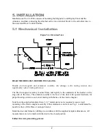
STEP 1 - FRAME PREPARATION
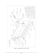
Remove the housing cover prior to lock installation (see Figure 5-5 Exploded View). Prepare the
frame for the electro-magnetic lock assembly by drilling for #14 sheet metal screws or drilling
and tapping for 1/4-20 machine screws and external tooth lock washers, (use the large slotted
holes only) tightening the screws just enough to hold unit in place. Route the attached 20 ft.
cable through the frame to the location where it will be connected to the cable going to the SIC.
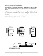
STEP 2 - ARMATURE PREPARATION (Figure 3)
Prepare armature for mounting: Note that the armature has two 3/16 dia. holes open from the back
only. Press the two spring pins provided into these holes. Tap pins gently until they are firmly seated
in the holes being extremely careful not to mar the face of the armature.
Insert one spring washer on the 5/16 #18 shoulder screw and then insert the screw thru the armature.
Add three conical spring washers over shoulder and flat stop washer. (Per diagram enclosed in
armature kit.)
STEP 3 - ARMATURE MOUNTING
THRU BOLT MOUNTING IN HOLLOW METAL DOORS (Figure 5-2A)
(Dimensions shown are for standard 1-3/4” thick doors)
Drill an 11/32” hole through the door. Enlarge the hole in the outside face to ½” for the knurled sex
nut. Be sure that the spring pins pocket and float freely in the ¼” holes in the door. If not, remove the
armature and enlarge the holes in the door. Insert the shoulder screw/armature assembly thru the face
of the door, being sure that the spring washers remain over the shoulder, and hold firmly against the
door by pushing directly on the head of screw. Insert the sex nut from the opposite face and assemble.
When the armature is floating freely, tighten the 5/16 #18 shoulder screw fully and securely with a
5/32 Allen wrench.
THRU BOLT MOUNTING IN SOLID CORE WOODEN DOOR (Figure 5-2B)
Drill a ½” hole through the door. Insert the shoulder screw/armature assembly thru the face of the
door, being sure that spring washers remain over the shoulder, and hold firmly against the door by
pushing directly on the head of the screw. Insert the sex nut from the opposite face and assemble.
When the armature is floating freely, tighten the 5/16 #18 shoulder screw fully and securely with a
5/32 Allen wrench.
MACHINE SCREW MOUNTING (Figure 5-2C)
The door must be properly reinforced to a 3/8” minimum thickness and structured for a 1200 lb. load.
Drill and tap thru the reinforcing for a 1/15 #18 machine screw. Insert the shoulder screw/armature
assembly, being sure that the spring washers remain over the shoulder and the flat washer is between
the shoulder and the face of door. When the armature is floating freely, tighten the 5/16 #18 shoulder
screw fully and securely with a 5/32 Allen wrench.

