13
7. THEORY OF OPERATION AND
TROUBLESHOOTING
General
The CC-8946 operates together with a Control Module located in a Security Information Center
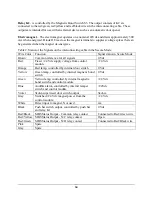
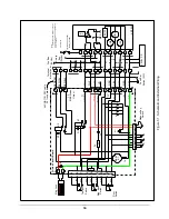
(SIC). Figure 7-1 is a schematic diagram of the Model CC-8946 showing the interconnections to
the Control Module in the SIC. It is supplied as an aid to understanding both the operation of the
CC-8946 itself and its connections to the Control Module.
Power to the magnetic lock is routed from the Control Module through T1, Pin 8, then through
the Key Switch S5 to the magnet.
Sensors within the CC-8946 monitor the status of the door, magnetic lock and push bar and route
this information to the control unit through T1 and the interconnecting cable. The Control
Module uses this information to control the magnetic lock and the status of the indicator lamps
and audible alarm on the CC-8946’s display panel.
Indicators and Audible Alarm
The three indicator lamps and the audible alarm all have one side connected to +24 Vdc from Pin
2 of T1. The other side of each device is controlled by both external connections to the Control
Module and by sensing switches within the CC-8946.
The Red lamp is controlled by the internal Door Switch (S4). When the door is open this switch
is closed, connecting the common return path to the red lamp.
The Green and Amber lamps are connected to the Magnetic Bond Switch S3. When the magnet
is energized and bonded to the armature, S3 connects the common return path to the Green lamp
L2. When the magnet and armature are not bonded, S3 connects the common return path to the
Amber lamp L3. The Control Module may also activate the Amber Lamp L3 by applying the
common return path through T1, Pin 5. This occurs during the Egress Request Mode.
Fuse F1 protects the magnetic bond reed switches against currents in excess of 200mA. These
reed switches are susceptible to damage if a voltage source is inadvertently applied during
installation. F1 automatically resets itself after the voltage causing the excess current to be
removed.
The Audible Alarm B1 is controlled by the Tamper Switch S2 and by the Control Module
through T1, Pin 6. The Tamper Switch S2 connects the common return path to B1 when the
cover of the CC-8946 is removed.
Test Switch
- Applies the common return path to all three lamps and B1 (through diodes D3,
D4, D5 and D6). This provides a means of testing the lamps and audible alarm. Note that this test
also activates the lamps and audible alarm on the Control Module.
Relay K1
- is controlled by the power to the magnet and its contacts shunt the external push bar
switch when the magnet is energized.

