


Molten Voltage™
CV-SYNC™
Owner’s Manual - p.6
© 2014 - MoltenVoltage.com - All Rights Reserved.
v 1.0
MIDI Phantom Power
CV-SYNC does not use MIDI Phantom Power.
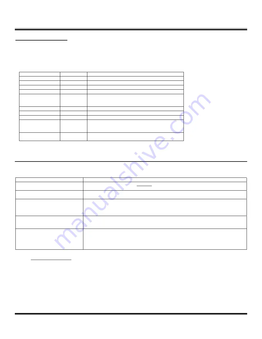
MIDI IMPLEMENTATION CHART
Function
Recognized
Comment
Note On
X
Note Off
X
Aftertouch
X
Control Change
X
Program Change
O
Only Program Changes on Channels 1 or 15
(depending on selection) recognized.
Channel Pressure
X
Pitch Bend
X
System Common
X
System Exclusive
O
Responds to Molten Voltage self-program
commands.
System Realtime
O
Only MIDI Start and Clock.
O = YES, X = NO
TROUBLESHOOTING
Problem
Solution
CV-SYNC will not turn on.
Plug in 9 volt DC, 2,1mm Tip Negative Power Supply.
Clicking or Noise
Use a
separate
or
isolated
Power Supply for CV-SYNC
CV-SYNC is not receiving MIDI
Clock
Make sure your other MIDI device is configured to send MIDI Clock. Consult the User’s
Guide for that device. If it cannot send MIDI Clock, consider the Molten Voltage devices
MASTER CONTROL or TEMPODE.
CV-SYNC not receiving MIDI
Program Change messages
Set your MIDI device to send MIDI Program Change messages on the same MIDI Channel
as CV-SYNC. (
see above
regarding Selecting MIDI Channel).
Connected Device is not
synchronized
Determine switching polarity required by referring to device’s owner’s manual, and adjust
CV-SYNC accordingly.
Make sure MIDI Clock and Ratio do not exceed the input limits of the device.
General Guidelines
Keep MIDI cables as short as possible. Long cables cause errors. If you need more length,
consider using a MIDI repeater.
If you are daisy chaining MIDI devices, the total MIDI cable length must be considered if
any MIDI devices do not amplify the data signal.


