CR60639B Hand Crimp Tool for “Min-Fit Jr.” Terminals
Doc No. 11-01-0198
Release Date: 04-08-93
UNCONTROLLED COPY
Page 2 of 5
Revision: E
Revision Date: 09-01-05
Figure 2
CONDITIONS:
After crimping, the conductor profiles should measure the following (see notes on page 4).
Punch Width (Ref)
Wire Size
Cond. Crimp Height
(Ref)
Cond. Ins.
Pull Force Min. Profile
Terminal Series No.
AWG mm
2
mm
In. mm
In.
mm
In. N Lb. A
B
5556-T2
22 0.35 0.76-0.86 .030-.034 1.42 .056 1.68 .066 40.0 9.00 X
5556-T2
24 0.20 0.69-0.79 .027-.031 1.42 .056 1.68 .066 31.1 7.00 X
5556-T2
26 0.12 0.64-0.74 .025-.029 1.42 .056 1.68 .066 22.2 5.00 X
5556-T2
28 0.08 0.61-0.71 .024-.028 1.42 .056 1.68 .066 13.3 3.00 X
5558-T2
22 0.35 0.76-0.86 .030-.034 1.42 .056 1.68 .066 40.0 9.00 X
5558-T2
24 0.20 0.69-0.79 .027-.031 1.42 .056 1.68 .066 31.1 7.00 X
5558-T2
26 0.12 0.64-0.74 .025-.029 1.42 .056 1.68 .066 22.2 5.00 X
5558-T2
28 0.08 0.61-0.71 .024-.028 1.42 .056 1.68 .066 13.3 3.00 X
OPERATION
Open the tool by squeezing the handles together, at the end of the closing stroke, the ratchet mechanism will release the handles,
and the hand tool will spring open.
Crimping Terminals
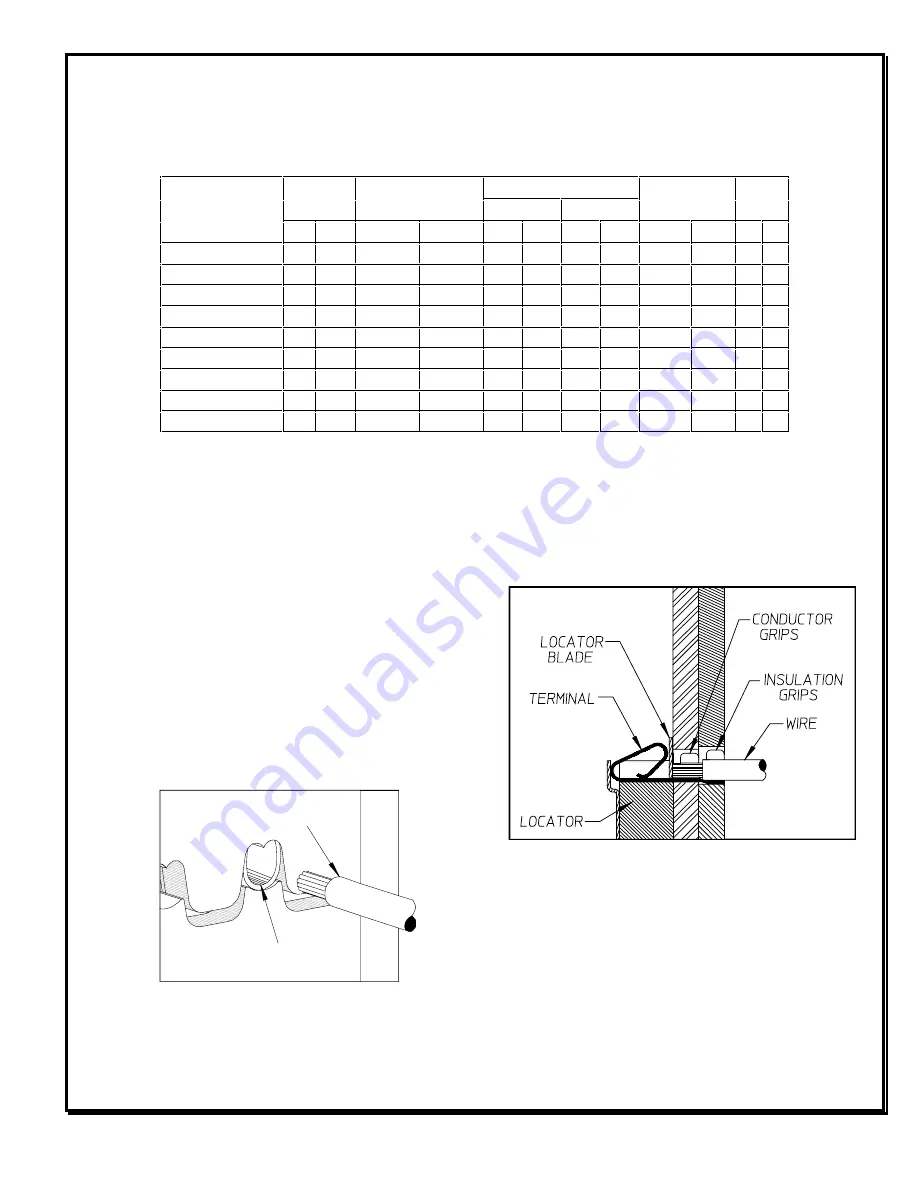
1. Lift the locator blade and place the terminal into the correct die
profile (A or B), release the locator blade. Not all tools are
equipped with a locator or locator blade.
2. Partially close the tool until the terminal is held in place, (See
Figure 1). If the insulation diameter is too large to do this, then
place the insulation down into the terminal before closing the
tool.
TERMINAL
PRE-STRIPPED WIRE
Figure 1


