background image

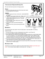
Hand Crimp Tool for Nano-Fit™ Crimp Terminals 

Doc No: ATS-6382760HM 

Release Date: 10-17-14 

UNCONTROLLED COPY


Page 2 of 7 

Revision: A 

Revision Date: 10-22-14 
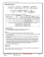
 

CRIMP SPECIFICATION 


Terminal Series No. 

Bell mouth 

Cut-off Tab Maximum 

Conductor Brush 

mm 

In. 

mm 

In. 

mm 

In. 

105300 

0.15 – 0.25  0.006 – 0.010 

0.17 

.007 

0.25 – 1.00  0.010 – 0.039 


Terminal Series No. 

Bend up  Bend down  Twist    Roll 

Seam


Seam shall not be open 

and no wire allowed out of 

the crimping area 

Degree 

Degree 

105300 

 
After crimping, the conductor profiles should measure the following. 

Terminal 

Series No 

Wire Size 

Conductor Crimp 

Insulation Crimp


Pull Force 

Minimum 

Profile 

Height 

Width (Ref.)  Height (Ref)  Width (Ref) 

A  B  C  D 

AWG  mm

2


mm 

In. 

mm 

In. 

mm 

In. 

mm  In. 

Lb.  24  24  26  26 

105300 

24 

0.70 – 0.75  0.027 – 0.030  1.15  0.045 

1.60  0.063  1.55  0.061 

22.3  5 


1.70  0.067  1.70  0.067 

  X   


26 

0.65 – 0.70  0.025 – 0.027  1.15  0.045 

1.55  0.061  1.55  0.061 

13.4  3 


  X   

1.65  0.065  1.70  0.067 


  X 

To Achieve IPC-A-620 Class 2 Crimps, the following over-all wire insulation diameter ranges are recommended: 

Profile A: (UL1061) 1.10mm – 1.20mm (0.043in – 0.047in) 
Profile B: (UL1007) 1.30mm – 1.40mm (0.051in – 0.055in) 
Profile C: (UL1061) 1.05mm – 1.15mm (0.041in – 0.045in) 

Profile D: (UL1007) 1.20mm – 1.30mm (0.047in – 0.051in)


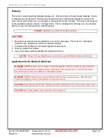
Tool Qualification Notes: 
1.


Pull Force should be measured with no influence from the insulation crimp. 

2.


The above specifications are guidelines to an optimum crimp. 


Notes: 

1.


This tool should only be used for the terminals and wire gauges specified on this sheet. 

2.


This tool is not adjustable for crimp height.  Variations in tools, terminals, wire stranding, and insulation types 
may affect crimp height. 

3.


This tool is intended for standard conductor sizes.  It may not give a good insulation crimp support for all 
insulation sizes. 

4.


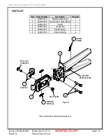
Molex does not repair hand tools (see warranty above).  The replacement parts listed are the only parts 
available for repair.  If the handles or crimp tooling is damaged or worn, a new tool must be purchased. 

5.


Pull force should be used as the final criteria for an acceptable crimp.  Pull force is measured with no 
influence from the insulation crimp.  The insulation should be stripped long (1/2 in.) so the insulation grips 

on the terminal do not grip the wire insulation or the conductor.  Refer to Molex Quality Crimping 
Handbook 63800-0029 for additional information on crimping and crimp testing. 

6.


Molex does not certify crimp hand tools. 
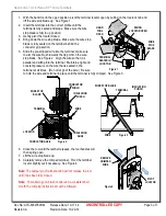
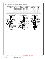
 

OPERATION 

 
Open the tool by squeezing the handles together, at the end of the closing stroke, the ratchet mechanism will 
release the handles, and the hand tool will spring open. 

Summary of Contents for 63827-6070

Page 1: ...liant as indicated and RoHS compliant Modular Crimp Head is removable and can be use in the Air Powered Tool Order No 63816 0100 accompanied by Air Powered Crimp Adapter Order No 63816 0700 Can also be used in the Battery Powered Tool Order No 63816 0200 110 V or 63816 0250 220 V accompanied by Battery Powered Crimp Adapter Order No 63816 0600 SCOPE Products Nano Fit Receptacle Terminals 24AWG and...

Page 2: ...D UL1007 1 20mm 1 30mm 0 047in 0 051in Tool Qualification Notes 1 Pull Force should be measured with no influence from the insulation crimp 2 The above specifications are guidelines to an optimum crimp Notes 1 This tool should only be used for the terminals and wire gauges specified on this sheet 2 This tool is not adjustable for crimp height Variations in tools terminals wire stranding and insula...

Page 3: ...osed 4 Bring down the wire stop blade Make sure the wire stop blade is fully seated on the terminal behind the conductor grip section 5 Slide the pre stripped wire into the terminal make sure to aim the wire brush towards the tip point on the wire stop blade See Figure 2 Align the wire so that it is parallel and sitting into the terminal Maintain a light and constant pressure on the wire that is s...

Page 4: ...e made aware of and responsible for the following maintenance steps 1 Remove dust moisture and other contaminants with a clean brush or soft lint free cloth 2 Do not use any abrasive materials that could damage the tool 3 Make certain all pins pivot points and bearing surfaces are protected with a thin coat of high quality machine oil Do not oil excessively The tool was engineered for durability b...

Page 5: ...pair This tool is NOT intended for production use Repetitive use of this tool should be avoided 2 Insulated rubber handles are not protection against electrical shock 3 Wear eye protection at all times 4 Use only the Molex terminals specified for crimping with this tool CAUTION Molex crimp specifications are valid only when used with Molex terminals and tooling Applications for the Modular Crimp H...

Page 6: ...ular Crimp Head Order No Tool Order no Tool Description Adapter Order No Adapter Description Figure No 63827 6070 63816 0000 Hand Crimp Frame Short N A N A 7 63816 0050 Hand Crimp Frame Long N A N A 7 63816 0200 Battery Power Tool 110 V 63816 0600 Battery Power Crimp Adapter 8 63816 0250 Battery Power Tool 220 V 63816 0600 Battery Power Crimp Adapter 8 63816 0100 Air Power Tool 63816 0700 Air Powe...

Page 7: ...EVER HANDLE SPRING CRIMPING SPRING 2 LOCATOR 2 1 4 Figure 10 M4 X 12mm LONG BHCS 3 5 6 M4 LOCKNUT PARTS LIST Item Order Number Description Quantity 1 63827 6070 Modular Crimp Head 1 2 63816 0000 Hand Crimp Frame Short 1 3 63827 6075 Locator 1 4 63816 0001 Locking Pin 2 5 63600 0525 Handle Spring 1 6 63600 0520 Crimping Spring 2 Visit our Web site at http www molex com ...

Reviews: