

63813-2100 Modular Card Extractor Tool
Doc No. 63813-2100
Release Date: 05-10--06
UNCONTROLLED COPY
Page 2 of 5
Revision: A
Revision Date: 05-10-06
PCB BOARD
Figure 2
MODULE CARD
METAL
LATCH
PUSHER
METAL
LATCH
PUSHER
MODULE HOUSING
MODULE CARD
LATCHES OPEN
METAL LATCH PUSHER
Figure 3
MODULE CARD
MODULE CARD
HOUSING
EXTRACTOR
TOOL
MODULE CARD
HOUSING
Figure 4
METAL LATCH
PUSHER
MODULE
CARD
MODULE CARD
LATCHES LOCKED
IN PLACE
LIFT UP BY
THE HANDLE
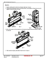
Operation
1. Align the metal latch pushers (2) with the slots on the module card housing. See Figure 2.
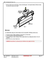
2. Push the extractor tool down and into the slots. The module card latches are spring-loaded and will open when extractor tool is
engaged in the module card housing. See Figure 3.
3. Make sure the extractor tool is firmly seated in the slots of the module card housing and the module card latches are locked into
the module card.
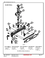
4. Pull the module card straight up with the handle of the extractor tool. See Figure 4.


