Greenlee 1904, Instruction Manual
The Greenlee 1904 Instruction Manual is your comprehensive guide to effectively operate and maintain your equipment. This manual is available for free download on our website, ensuring easy access for all users. Get the most out of your product by obtaining the necessary knowledge and instructions for optimal performance.
Share
Download


Reviews:
No comments
Related manuals for 1904

FP Series
Brand: Hammer Pages: 40

CDD 12V PLUS
Brand: F.F. Group Pages: 44

BlackFin CT-2980
Brand: Panduit Pages: 12

PHDE 72
Brand: Milwaukee Pages: 4

RBE 12-180
Brand: Metabo Pages: 72

SDP 1
Brand: RAMSET Pages: 12
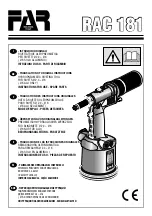
RAC 181
Brand: FAR Pages: 76

PNEUTORQUE PTM series
Brand: norbar Pages: 26

Akku-Press 22 V ACC
Brand: REMS Pages: 212

SpinTORQ
Brand: Fastorq Pages: 6

28050
Brand: FESTA Pages: 42

G0834
Brand: Grizzly Pages: 60

8120 Series
Brand: Alemite Pages: 6

E-649RA
Brand: Scell-it Pages: 20

25 78 32
Brand: Westfalia Pages: 19

7063826
Brand: Batavia Pages: 32

IR25BS
Brand: Ingersoll-Rand Pages: 56

TiQL
Brand: Tohnichi Pages: 8


