


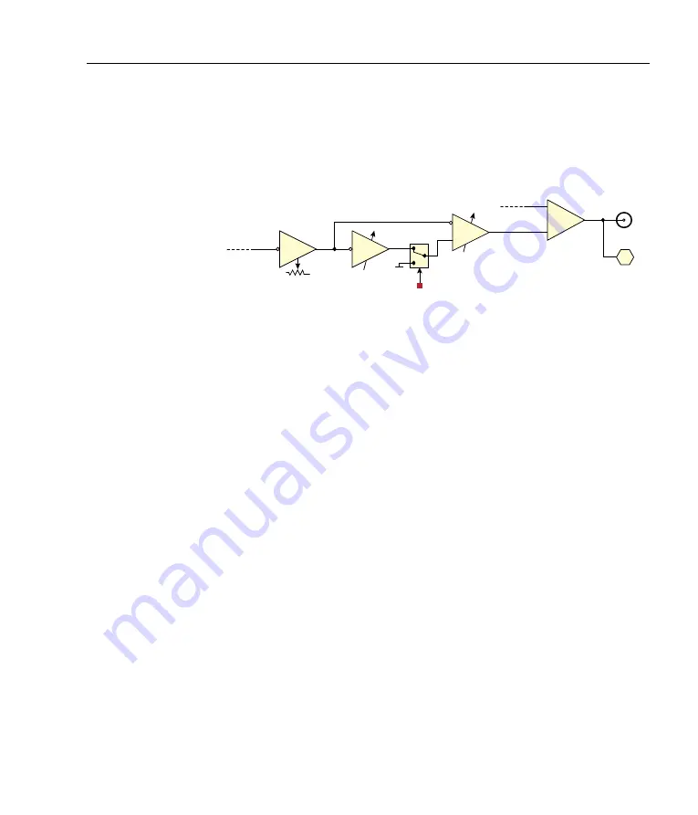
3.2 Slow servo loop
15
depending on whether
DIP2
is enabled. The slow integrator time
constant is controlled from the front-panel
SLOW INT
knob, which is
labelled in terms of the associated corner frequency.
Double integrator [2]
Slow error
SLOW SERVO
Gain
SLOW GAIN
0v
∫
#1
∫
#2
SLOW OUT
+
LF sweep
LF
SLOW
Integrators
SLOW INT
SLOW INT
Figure 3.3:
Schematic of slow feedback
I
/
I
2
servo. Hexagons are monitored
signals available via the front-panel selector switches.
With a single integrator, the gain increases with lower Fourier fre-
quency, with slope of 20 dB per decade. Adding a second integrator
increases the slope to 40 dB per decade, reducing the long-term off-
set between actual and setpoint frequencies. Increasing the gain too
far results in oscillation as the controller “overreacts” to changes in
the error signal. For this reason it is sometimes beneficial to re-
strict the gain of the control loop at low frequencies, where a large
response can cause a laser mode-hop.
The slow servo provides large range to compensate for long-term
drifts and acoustic perturbations, and the fast actuator has small
range but high bandwidth to compensate for rapid disturbances. Us-
ing a double-integrator ensures that the slow servo has the dominant
response at low frequency.
For applications that do not include a separate slow actuator, the
slow control signal (single or double integrated error) can be added
to the fast by setting the
SLOW
switch to “
NESTED
”. In this mode it
is recommended that the double-integrator in the slow channel be
disabled with
DIP2
to prevent triple-integration.


