background image

2-506.14

OPERATION

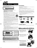
Figure 9.1 - Cutaway of Electric Unit Heater

2

1

7

8

9

6

5

4

3

Operating Sequence

The operation of Modine electric unit heaters is governed by 

an electrical contactor which is controlled by a thermostat. The 

contactor completes the electric circuit to the heating elements 

when the thermostat “calls” for heat. The fan motor is also 

activated when the thermostat “calls” for heat.
When the thermostat is satisfied, the fan motor stops and the 

contactor opens the circuit to the heating elements.

Prior to Operation

Although this unit has been inspected and tested at the factory, 

the following procedures should be performed to assure proper 

on-site operation.
1.  Check fan clearance. Fan should not contact casing or fan 

guard when spun by hand.

2.  Check all electrical connections to be sure they are secure, 

and in accordance with the wiring diagram.

3.  Check firmness of unit suspension. Tighten all fasteners, if 

necessary.

4.  Make sure fuses are installed in units that require them.

Safety Devices

The overheat control, (See Figure 9.1), will interrupt power to 

the unit contactor in the event of overheating. It is a single-pole 

single-throw switch, with an automatic reset. The switch will 

permit the motor to continue operation and cool the heater while 

power to the elements is interrupted. This overheat control 

should operate only when something is seriously wrong 

with the unit. When this control operates, correct the 

difficulty immediately or serious and permanent damage 

may result.

The motor for the circulating air fan has internal thermal 

overload protection. If for any reason, the motor overheats, 

the thermal protector will shut it off. The motor will re-start 

automatically when it has cooled.

Initial Start-Up

1.  Adjust room thermostat above room temperatures.
2.  Turn on power to the unit.
3.  Adjust the air deflector (if provided) for desired heat 

distribution.

4.  Run the unit through several cycles by raising and lowering 

the thermostat setting to assure proper sequence of 

operation. For Models VE and PTE300, 400, 500 with 

two-stage thermostats, check operation on both states. 

Three elements should heat up during first stage operation 

when temperature falls. As additional heat is required 

the remaining three elements will be energized until the 

thermostat high-stage setting is satisfied. The unit will 

automatically shut off when the low-stage thermostat setting 

is satisfied.

1. Side terminal box

2. Power junction box

3. Heating elements

4. Motor heat shield

5. Element support

6. Protective screen

7. Overheat control

8. Fan and motor

9. Outlet fan guard

9

Summary of Contents for PTE

Page 1: ...at installer s risk For replacement parts submit the unit heater model number power code control code and serial number shown on the rating plate attached to the unit Do not remove outlet fan guard from vertical electric unit heaters except to service the unit Contents General Information 1 Installation Special Precautions Important Instructions 2 Unit Locations 3 Ceiling Suspension 4 5 Wall Mount...

Page 2: ...pany Refer to the rating plate on the appliance for complete appliance model number serial number and company address Any substitution of parts or controls not approved by the factory will be at the owner s risk 5 Do not operate any heater if it malfunctions Disconnect power at service panel and have heater inspected by a qualified installation and service agency CAUTION 1 All literature shipped w...

Page 3: ...above which the unit will not deliver heated air to the floor The maximum mounting heights must not be exceeded in order to assure maximum comfort WITH CONE JET WITHOUT DEFLECTOR S H S S H H T T H H S H WITH LOUVERS WITH TRUNCONE Figure 3 3 Vertical Delivery Heat Spread Throw Unit Mounting CAUTION 1 Do not install VE type unit heaters closer than 18 inches from ceiling and 24 inches horizontally f...

Page 4: ...capscrews to facilitate threaded pipe suspension Two kits are required to pipe mount a vertical unit Kit is not available on 480 volt models VE50 thru VE250 with transformer junction box INSTALLATION Figure 4 4 Ceiling mounted Model PTE Figure 4 1 Vertical Model VE with Cone Jet Accessory Installed ANGLE BRACKET FASTENING Figure 4 2 Horizontal Delivery with Louver Deflectors Models PTE300 PTE400 P...

Page 5: ... bracket saves installation time has a built in wall clearance and provides an inexpensive and convenient wall mounting method The one point suspension shown above permits swiveling the unit 180 degrees horizontally for most effective air direction Refer to separate bulletin included in the kit for bracket assembly and installation Refer to Figure 4 2 for maximum mounting heights Minimum mounting ...

Page 6: ...EARANCES AT LEAST 18 FROM CEILING AND 24 HORIZONTALLY FROM NEAREST ENCLOSURE 7 8 DIA FOR CONTROL WIRING 4 MTG HOLES 1 2 13 N C TAP Figure 6 2 Outline Dimensions PTE Models 12 18 24 24 MIN CEILING WALL 5 18 MIN 6 25 3 8 34 7 8 20 5 8 8 5 8 5 3 4 7 8 OPENING FOR CONTROL WIRING HANGER BRACKET 4 PROVIDED 4 MTG HOLES FRONT AND REAR 5 8 DIA 1 3 8 OPENING FOR POWER SUPPLY Table 6 3 Motor Specifications T...

Page 7: ...t The unit may also be controlled by a remote manual on off switch Control wiring should be No 14 AWG American Wire Gauge Total line amperes in Table 8 1 includes fan motor and element current FLA Refer to Table 6 3 for motor current draw All 480 volt three phase units have built in transformers and fuses to stepdown voltage and protect motor and control circuit Fuse blocks with fuses are factory ...

Page 8: ...so provide closer temperature control Models VE and PTE 300 400 500 cannot operate in two stages with this control and a low voltage thermostat but will respond with full operation of all elements OVERHEAT CONTROL ELEMENT CONNECTION Model Volume VE50 thru 100 3 029 cm3 VE150 thru 250 2 883 cm3 VE PTE300 thru 500 9 570 cm3 JUNCTION BOX POWER SUPPLY OPENING THERMOSTAT WIRING OPENING Table 8 2 Power ...

Page 9: ... switch will permit the motor to continue operation and cool the heater while power to the elements is interrupted This overheat control should operate only when something is seriously wrong with the unit When this control operates correct the difficulty immediately or serious and permanent damage may result The motor for the circulating air fan has internal thermal overload protection If for any ...

Page 10: ...not have oil fitting These are lubricated for long life and do not require further lubrication 6 Routine cleaning of the outer unit casing and protective screen is recommended to remove dirt grease or corrosive material that may damage finish Rusted or corroded spots on top or bottom casing should be sanded and repainted 7 Clean fan blades elements and inside casing with either a detergent solutio...

Page 11: ...ing and connections check continuity through control Replace if necessary 2 Summer winter switch in 2 Change switch position summer position 3 Defective or incorrect wiring 3 Check all wiring and connections See diagram inside junction box 4 Blown element fuses 4 Replace element fuses Elements heat but fan 1 Fan motor failure 1 a Check for loose electrical connections does not operate Check wiring...

Page 12: ...D IN HIGH HUMIDITY APPLICATIONS AND UTILIZING STAINLESS STEEL HEAT EXCHANGERS BUYER S REMEDY FOR BREACH AS LIMITED HEREIN SHALL BE LIMITED TO TEN YEARS FROM DATE OF SHIPMENT FROM SELLER These warranties are issued only to the original owner user and cannot be transferred or assigned No provision is made in these warranties for any labor allowance or field labor participation Seller will not honor ...

Reviews: