


Length
of Pipe
(feet)
Natural
Propane
Natural
Propane
Natural
Propane
Natural
Propane
Natural Propane
Natural
Propane
10 132 83 278 175 520 328
1050 662 1600
1008
3050
1922
20
92
58
190
120
350
221
730
460
1100
693
2100
1323
30
73
46
152
96
285
180
590
372
890
561
1650
1040
40 63 40 130 82 245 154 500 315 760 479 1450 914
50 56 35 115 82 215 135 440 277 670 422 1270 800
60 50 32 105 66 195 123 400 252 610 384 1150 725
70 46 29 96 60 180 113
370 233 560
353
1050
662
80 43 27 90 57 170 107 350 221 530 334 930 586
100 38 24 79 50 150 95 305 192 460
290
870
548
125 34 21 72 45 130 82 275 173 410
258
780
491
150 31 20 64 40 120 76 250 158 380
239
710
447
1.
Installation of piping must conform with local building codes,
or in the absence of local codes, with the National Fuel Gas
Code, ANSI Z223.1 (NFPA 54) - latest Edition. In Canada,
installation must be in accordance with CSA 149.1.
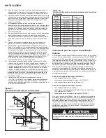
2.
Piping to units should conform with local and national
requirements for type and volume of gas handled, and
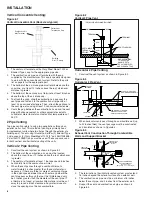
pressure drop allowed in the line.Refer to Table 13.1 to
determine the cubic feet per hour (CFH) for the type of gas
and size of unit to be installed. Using this CFH value and
the length of pipe necessary, determine the pipe diameter
from Table 9.1. Where several units are served by the
same main, the total capacity, CFH and length of main must
be considered. Avoid pipe sizes smaller than 1/2". Table
9.1 allows for a 0.3" W.C. pressure drop in the supply
pressure from the building main to the unit. The inlet
pressure to the unit must be 6-7" W.C. for natural gas and
11-14" W.C. for propane gas. When sizing the inlet gas pipe
diameter, make sure that the unit supply pressure can be
met after the 0.3" W.C. has been subtracted. If the 0.3"
W.C. pressure drop is too high, refer to the Gas Engineer’s
Handbook for other gas pipe capacities.
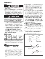
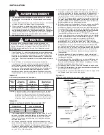
3.
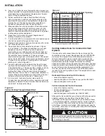
Install a ground joint union with brass seat and a manual
shut-off valve adjacent to the unit for emergency shut-off
and easy servicing of controls, including a 1/8" NPT
plugged tapping accessible for test gauge connection
(See Figure 9.1). Verify the manual shut-off valve is
gas tight on an anual basis.
4.
Provide a sediment trap before each unit in the line where
low spots cannot be avoided. (See Figure 9.1).
5.
When Pressure/Leak testing, pressures above 14" W.C.
(1/2 psi), close the field installed shut-off valve, disconnect
the appliance and its combination gas control from the
gas supply line, and plug the supply line before testing.
When testing pressures 14" W.C. (1/2 psi) or below, close
the manual shut-off valve on the appliance before testing.
9
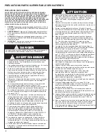
WARNING
1. All field gas piping must be pressure/leak tested prior to
operation. Never use an open flame. Use a soap solution
or equilavent for testing.
2. Gas pressure to appliance controls must never exceed 14"
W.C. (1/2 psi).
3. To reduce the opportunity for condensation, the minimum
sea level input to the appliance, as indicated on the serial
plate, must not be less than 5% below the rated input, or 5%
below the minimum rated input of duel rated units.
CAUTION
1. Purging of air from gas lines should be performed as
described in ANSI Z223.1 - latest edition “National Fuel
Gas Code”, or in Canada CSA B149.1 codes.
2. When leak testing the gas supply piping system, the
appliance and its combination gas control must be isolated
during any pressure testing in excess of 14" W.C. (1/2 psi).
3. The unit should be isolated from the gas supply piping
system by closing its field installed manual shut-off
valve.This manual shut-off valve should be located within
6' of the heater.
4. Turn off all gas before installing appliance.
Figure 9.1
Recommended Sediment Trap/Manual Shut-off Valve
Installation - Side or Bottom Gas Connection
GAS
SUPPLY LINE
GAS
SUPPLY LINE
GROUND
JOINT
UNION
MANUAL
SHUT-OFF
VALVE
3"
MIN.
SEDIMENT
TRAP
PLUGGED
1/8" NPT TEST
GAGE CONNECTION
TO
CONTROLS
➀
Manual shut-off valve is in the “OFF” position when handle is perpendicular to pipe.
INSTALLATION
Gas Connections
Table 9.1
Gas Pipe Capacities
1/2"
3/4"
1"
1-1/4"
1-1/2"
2"
Pipe Diameter
IMPORTANT
To prevent premature heat exchanger failure, the input to the
appliance, as indicated on the serial plate, must not exceed
the rated input by more than 5%.
Gas Pipe Capacities (Up to 14 W.C. Gas Pressure through Schedule 40 Pipe)
Cubic Feet per Hour with Pressure Drop of 0.3 W.C.
Natural Gas - Specific Gravity - 0.60
Propane Gas - Specific Gravity - 1.50


