


10
6-563.7
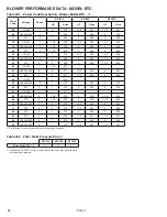
Drip Leg for Canada
(Alternate for US)
(refer to Note C3.c.)
InsTAllATIon - venTIng
figure 10.1 - Horizontal venting system drip leg and Condensate drain Connections
section C - Horizontal vent system Installation
C1. This section applies to horizontally vented 2-pipe vent
systems (1 combustion air inlet pipe and 1 vent pipe) and
concentric (single wall penetration) and is in addition to
“Section A - General Instructions - All Units”.
C2. Horizontal vent systems terminate horizontally (sideways).
C3. It is required to install a tee with drip leg and clean out cap
as shown in Figure 10.1. Please note the following
requirements:
a. Only the vent system drip leg and condensate removal
drain connections are shown. Vent and combustion air
piping must be terminated per the instructions in this
manual, for either 2-pipe or horizontal concentric vent
arrangements. All venting and drain components, except
condensate traps, are by others.
b. The standard vent drip leg and drain shown for US ONLY
installations utilizes a tee, sized to match the vent diameter
for the model size (see Table 6.1). The tee captures and
directs the condensate to a cap that is drilled and fitted
with a 3/4” fitting for connection to the condensate drain.
For installation in Canada, see Note C3c.
c. The vent drip leg for Canadian installations must be
approved to ULC S636. This requires the use of a series
of reducers from the outlet of the tee to the drain
connection. Drilling or otherwise modifying the shape or
structure of any vent components is not allowed per
ULC S636. Note that the 3/4" condensate drain piping
and condensate traps are not subject to the ULC S636
requirements that apply to the vent system. This method
is also acceptable in US installations.
d. Connection of a combustion air inlet pipe is required to
be connected from the building exterior (not shown in
Figure 10.1)
e. A condensate drain each is required from the unit heater
and the vent system. Properly sized traps are included
with the unit. Proper drain design and installation is
critical to ensure that the unit and vent systems are
properly drained. Refer to the section titled “Condensate
Drain and Trap Installation” on page 13 for detailed
instructions.
C4. If a concentric vent system is to pass through one
common hole in the wall, please proceed at this point to
“Section D - Horizontal and Vertical Concentric Venting”
for instructions. Otherwise, proceed to note C5 for
instructions on terminating a 2-pipe installation.
C5. For 2-pipe horizontal configurations, refer to the following
instructions and Figure 11.1 with minimum distances as
shown.
C6. The vent pipe for all sizes except 260 must be terminated
with a PVC 90° elbow with screened opening. The vent
pipe for model size 260 must be terminated with a PVC
tee with screened openings. These screens are available
from Modine as part of a kit.
C7. For all sizes except 260, the elbow is to be installed on
the vent pipe outlet so that the elbow is at a 45° angle
with the opening facing away from the combustion air
inlet pipe. For model size 260 units, the tee is to be
installed horizontally so that the openings of the tee face
right and left.
C8. The combustion air inlet pipe termination is to be a 90°
elbow with screened opening. These screens are
available from Modine as part of a kit. For model sizes
260 and smaller, the elbow is to be PVC. For model size
310, the elbow is to be galvanized or other approved
corrosion resistant metal elbow.
C9. The elbow is to be installed on the combustion air inlet
pipe with the opening of the elbow facing down.
C10. When condensation may be a problem, the vent system
shall not terminate over public walkways or over an area
where condensate or vapor could create a nuisance or
hazard or could be detrimental to the operation of
regulators, relief openings, or other equipment.
C11. Maintain a 1/4" per foot upward slope away from the
heater and place a drip leg with clean out near the vent
connector on the heater as shown in Figure 10.1.
C12. For a vent termination located under an eave, the
distance of the overhang must not exceed 24". The
clearance to combustibles above the exterior vent must
be maintained at a minimum of 12". Consult the National
Fuel Gas Code for additional requirements for eaves that
have ventilation openings.
C13. Once venting is complete, proceed section titled
“Condensate Drain and Trap Installation” on page 13.
To Building
Exterior
(refer to
Note C3.a.)
Pitch vent pipe
up 1/4" per foot
(refer to Note C11)
Drain and trap to
sanitary sewer
connection for
condensate removal.
➀
(refer to Note C3.e.)
Combustion Air Inlet
Pipe Connector
(refer to Note C3.d.)
Standard Vent
Drip Leg for
US ONLY
(refer to Note C3.b.)
➀
Proper drain design and installation is critical to ensure that the unit and vent systems are properly drained.


