Model Shipways H.M.S. Bounty's Launch 1789 Instruction Manual Download Page 10

10

STAGE 2:

BENDING ON THE FRAMES

Now we are going to have some fun bending on the frames.  As 
previously noted this method of boat building is as in full size 
practice for this size and type of boat hull.  Molds were set up at 
stations just as we have for the model and frames were steam bent
around them.  This is a good time to note that our building jig is
not part of the boat!  A word of caution, we do not want any part of
the boat to end up glued to the building jig.  Therefore it is a good
idea to wax the edges of the molds lest a drop of glue later run down
and wick in between a frame and a mold.  You can use paste wax,
beeswax, a candle or any other suitable wax you have around.  For
the prototype a paste furniture wax applied with a brush was used.
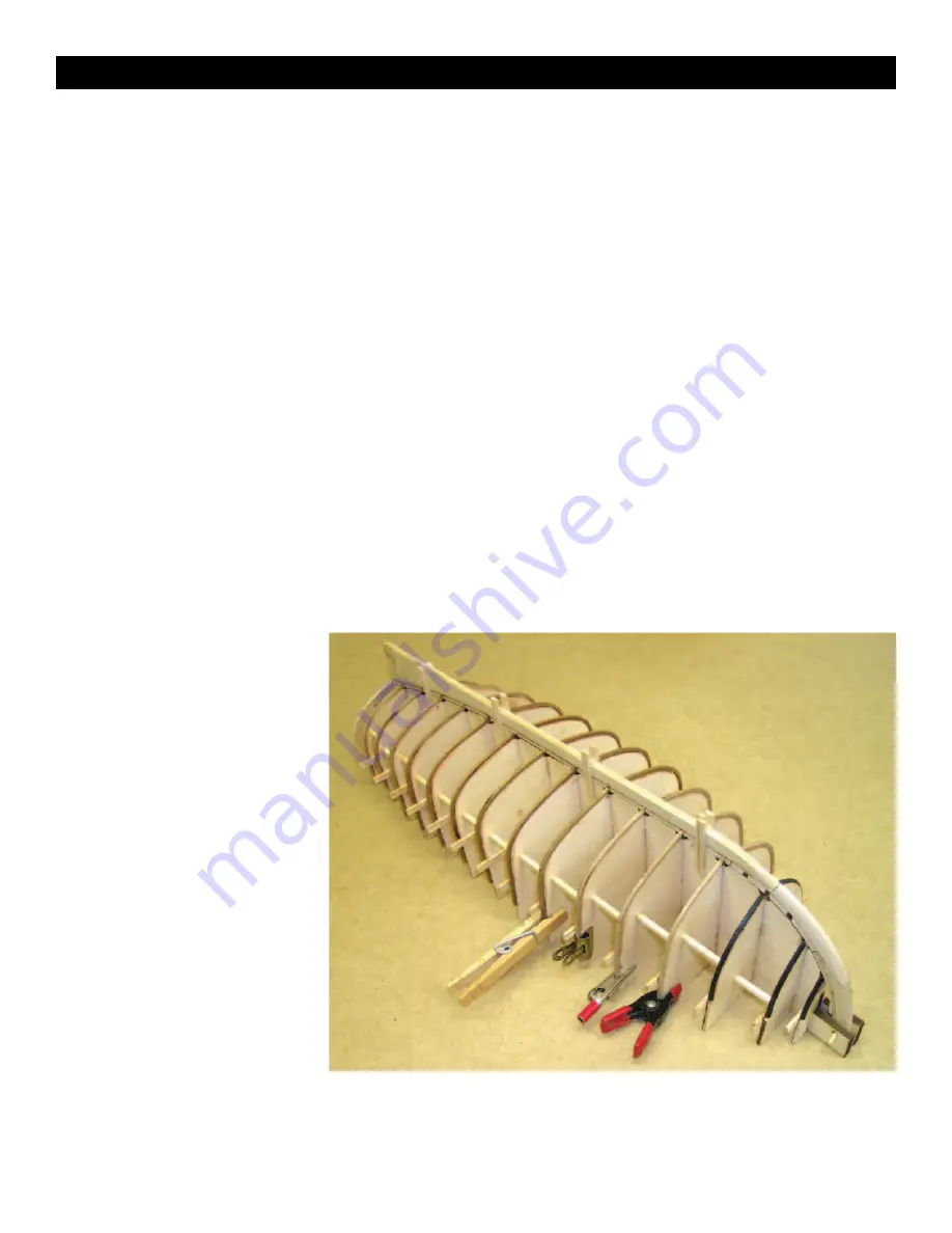
Also a reminder that molds 1, 2, and 3, do not take frames.  These
only provide shape to the bow of the boat and are lofted to the
inside of the planking, not the inside of the frames.  Note in photo
10 these molds have been colored to remind the builder that planks
are not to be glued to these molds.  

Some comments on bending wood.  Building the launch requires
quite a lot of wood bending.  Namely, the frames, planks, sheer
clamps, thwart risers, and floorboards.   What we are after is to 
pre-bend each piece of wood so that it will lie in it’s intended place
without undue force and/or distortion, and with a minimal amount
of persuasion.  Not doing so stresses glue joints and makes the
pieces difficult to install and clamp. Wood is bent by: 

Steam bending:

Hold the plank over a kettle of boiling water and

bend. Hold the wood in position until it cools. Although the plank
should remain in that shape, it may spring back slightly.  Gloves are
desirable, hot steam can severely burn.

Microwave steaming:

Wrap the planks in a

wet paper towel before heating. Since
microwaves differ in wattage, experiment to
determine what power level to use and for
how long.  Experiment with scrap pieces first
as it is quite possible to start a fire in your
microwave:

Soaking:

Submerge the plank in warm 

water for several hours. Try adding a little
household or pure ammonia. This speeds up
the process, making the fibers slippery so the
wood bends more easily. After soaking, and
bending, clamp the plank in its intended
position until completely dry.

Soldering iron:

Large soldering irons with a

tubular end are ideal. Clamp the iron
upright in a vise. While the iron heats, soak
the strip of wood in tap water. Some model-
ers prefer bending around the tube near the
handle (it’s not as hot), while others use the
shank. Move the strip back and forth against
the iron. Its heat turns water into steam and
drives it into the wood. The trick is to wait
until you feel the wood wanting to yield
before starting the bend. Begin too soon or
apply too much pressure and the strip will break. The wood dries
rapidly, so care must be taken to avoid scorching. Re-soak and reap-
ply it to the iron until the desired shape is achieved. Once the piece

is formed, it can go directly on the model. Because the wood’s 
memory has been permanently altered, it will never spring back to
its former shape, meaning no stress on any timber or fasteners.
Spend some time acquainting yourself with this method and you’ll
never bother with fixtures again.

Another soldering iron approach is to lathe-turn a tip from hard 
aluminum, then file a 45° angle on one end. Insert the tip in a 
20- or 30-watt soldering iron and heat it. Soak the wood for five
minutes, then let dry for five minutes. (Woods take on water faster
than they can release it.) Hold the tip against the wood to heat it.
When supple, bend the plank over a form, or simply lift the end as
heat is applied and bend by hand.

Commercial plank benders:

Model Expo sells an electric plank

bender designed for controlled heat, item no. MS7205. Another
tool (Amati’s FormAStrip available from Model Expo) bends planks
without soaking or heating. It looks like a pair of pliers with one flat
jaw and a chisel for the other. When squeezed on a plank, the chisel
depresses one side of the wood, causing it to bend. Repeat the
process along the plank until it assumes the correct curve. However,
squeezing too hard will cut the wood in half. This tool bends planks
in only one direction, so it’s good for bow planks, but not those at
the stern that are concave.  This treatment is not recommended for
the launch since unlike a plank on bulkhead hull, our planks are 
visible on the interior of the hull.  

The frame stock supplied in the kit is 3/32 square cherry.  Cherry
bends much more readily when hot and wet than does basswood.
The prototype model was built by soaking each frame in boiling

water for about 5 minutes.  This can be as simple as a coffee can of
water boiling on the kitchen stove.  What ever method you use it is
useful to begin bending and shaping a frame in your fingers before

Photo 10, frames 4 through 15 bent and installed


Summary of Contents for H.M.S. Bounty's Launch 1789

Page 1: ...y Model Shipways Inc Hollywood Florida Technical Characteristics Scale 3 4 1 0 1 16 Overall length 17 1 4 438 3mm Height from bottom of keel with masts 14 3 8 365mm Beam 5 3 8 136 5mm MODELING THE H M S BOUNTY S LAUNCH 1789 Kit design instructions and prototype model by Bob Crane 2006 Model Shipways Inc ...

Page 2: ...The last was the fate of three of them Knowledge of the extraordinary adventure that followed is due to the fact that Bligh kept a log and submitted it to the admiral ty after his return to England It recounts the events of the 4000 plus mile small boat voyage that took place after the mutiny and recounts as Bligh notes a voyage that was one of the most extraordinary nature that ever happened in t...

Page 3: ...haping and Tapering Masts Spars 18 2 Sail Making 18 3 Blocks 19 4 Lines 19 5 Boat Gear 19 Stage 6 Displaying Your Model 20 Bibliography 20 Table of Contents Table of Contents crowded into this small craft navigating through tall seas under sail The model construction method is in the traditional fashion for carvel planked hulls of this size upside down with a form or mold at each station The frame...

Page 4: ...t imagine performing the task and use logic 3 Understanding Hull Lines Beginners may not be familiar with the following hull lines Buttock lines are vertical longitudinal planes cutting through the hull Waterlines are horizontal planes and Sections are transverse vertical planes Diagonals are planes cut almost perpendicular to the station lines These lines define the hull s shape and are used by t...

Page 5: ...ng fine wire and strip metal H Sandpaper 1 Fine medium grit garnet or 100 to 220 aluminum oxide 2 400 wet or dry sandpaper 3 The sanding sticks sold for fingernail care are excellent and very handy These have medium and fine sandpaper and a foam core great for most sanding tasks I Sail Cloth Light weave cotton or linen cloth if sails are desired For furled sails a light material such as Silkspan i...

Page 6: ...be careful to avoid runs Spray on several light coats Most paint manufacturers have special thinners for their various paint lines Follow each manufacturer s recommendations Mixing brands is not a good idea because they may not be compatible Sometimes however no other option exists If so apply each brand separately and allow to thoroughly dry before adding the next Always test to make sure the fin...

Page 7: ... shown in photo 1 above will help you to align the pieces Assemble and glue together the 3 pieces stem keel and sternpost Note that the sternpost is a single piece of laser cut 3 16 thick basswood Do this over the plans on sheet 2 as shown in photo 2 below It is more important that the inside curve of the assembly match the plans than that the scarf joints are a tight fit Any gaps in the joints ca...

Page 8: ...ngraved rabbet line makes this a simple task Take care in the cutting to preserve the crisp engraved rabbet line Mark the rabbet line on the sternpost and carry the rabbet groove through the sternpost as shown on sheet 2 A pattern for marking the tapered portion of the stem is provided on sheet 2 Your options here are to cut the pattern out of the plans or trace the pattern on tracing paper or hav...

Page 9: ...ious when we begin to bend on the frames Molds 1 2 and 3 require the most material removal in the fairing process Fitting the keel the keel alignment tabs Once you are satisfied with your fairing test fit the keel assembly to the jig structure Molds 1 2 and 3 may require trimming a bit in way of the keel assembly to allow it to lie directly on the center keel Align the frame heel notches in the ke...

Page 10: ...re ideal Clamp the iron upright in a vise While the iron heats soak the strip of wood in tap water Some model ers prefer bending around the tube near the handle it s not as hot while others use the shank Move the strip back and forth against the iron Its heat turns water into steam and drives it into the wood The trick is to wait until you feel the wood wanting to yield before starting the bend Be...

Page 11: ...tock in the kit Cut a supply of 3 32 square frame stock to about 4 1 2 inches length This length is suitable for all frames except molds 15 and 14 which require a slightly shorter length Frames are bent by hooking the keel end under the keel in the sockets about halfway through and then wrapping the frames down over the mold and clamping them below the sheer tabs Refer to sheet 2 hull con structio...

Page 12: ...e on the hood end pattern Photo 12 making clamps from binder clips Photo 13 plank hood end locating pattern The garboard must be carefully aligned as shown on sheet 2 The garboard twists quite a bit where it meets the rabbet requiring more care to locate it properly Study the illustration on sheet 2 showing the placement of the garboard A straight edge aligned along the mark on the pattern may hel...

Page 13: ...ing is done time to sit back and admire your work You may wish to rough sand the hull at this point while it is still attached to the building jig Remove the pins from the transom and the dowel from the stem alignment blocks Using your knife work the blade in between the frames and the molds and pop the spot glued frames from the molds If you have not glued the hull to the building jig somewhere t...

Page 14: ...rboard for a total of 52 Now is the time to clean up any glue gobs Very little of the frames are visible in the finished model Review the plans and photos and concentrate on those areas of frame and plank that will be visible 2 Installing the sheer clamps The sheer clamps are 3 32 x 3 16 basswood strips that run along the sheer inside of the frames Refer to sheet 3 and photo 19 Prepare a landing f...

Page 15: ...ep requires a little more shaping as shown on the plans Its position is important as this will determine the relationship between the fit of the bow grate fore thwart and the foremast rake angle if any The sources used to design this model show the mast rake angle with the vertical both in a slightly raked and no rake configuration The choice is yours The prototype model was built with a slight ra...

Page 16: ... match the hull paint scheme The water line can be marked by turning the hull upside down and blocking it up on a flat surface A pencil clamped to a vertical member at the appropriate height is used to mark the location of the water line on the hull It is better to make a few spaced marks say every inch or so than to attempt to scribe the entire line 7 Mounting cradle A ship s boat like the launch...

Page 17: ... the rudder installation by locating and installing the upper gudgeon on the transom Drill and install with brass pins The pins should come out under the aft thwart and thus are not visible Fit the upper pintle to the rudder and engage the pintle pin in the gudgeon Clamp the pin tle to the rudder remove and drill through a pin hole Place a pin through the holes and put a slight bend in the protrud...

Page 18: ...be made is grossly out of scale This fact is just simply accepted by some as an inevitable fact and they prefer the look of sewn sails in spite of over scale stitches and fabrics Others devise various methods to attempt to make sails look realistic on a model Two methods are presented here the sewing method and a simplified method wherein the seams hems and reinforcements are represented by simple...

Page 19: ...bly carried with them some personal gear likely carried in bags There was sufficient extra canvas aboard for the rigging of weather cloths around the boat to increase the freeboard He also had sufficient extra rope for the rigging of shrouds to the masts The boat as issued had no shrouds A grapnel for anchoring was aboard Boat gear supplied in the kit and illustrated in the photo below may be arra...

Page 20: ...Jim Roberts Hollywood FL Model Shipways Inc 1987 Topnotch publication on how to plank ships from all periods Designed to help the kit builder if the plans don t show a planking scheme Ship Modeler s Shop Notes edited by Merritt Edson Jr and others Nautical Research Guild 1979 Valuable collection of shop hints and articles extracted from early issues of the Nautical Research Journal Many quality il...

Reviews: