background image

16

Plan Sheet 3 shows all the details for construct-
ing the basic fuselage. The plan also shows the
cross bracing wires for the fuselage and the alu-
minum cockpit cowl. However, do not install
the cockpit cowl or any brace wires that would
interfere with installing cockpit controls. The
cowl and some wires would get in the way
when installing cockpit controls, seats, etc. The
instrument panel fittings should be installed
during this stage, as it is easier to place these in
the instrument panel formers before the form-
ers are installed. The landing gear, remaining
cockpit controls, and engine installation will
also be discussed in later stages. The following
parts are required for this stage:

Laser-Cut Wood Parts

Forward instrument panel former – 1 of F1
Aft instrument panel former– 1 of F2
Turtleback formers – 1 each of F3 through
F10
Fuselage building jig center piece – 1 of F26
Fuselage building jig formers – 1 each of
F27 through F32

Britannia Castings

Oil pressure gauges – 2 of E1
Altimeters – 2 of E2
Ignition Switch – 1 of E3
Air speed indicator – 1 of E4
Tachometer – 1 of E5
Water temperature gauge – 1 of E6

Photo-Etched Copper Parts

Double eye cross brace wire fitting – 24 
of F11
Triple eye cross brace wire fitting – 18 
of F12
Strut clips Station 6 thru11 – 24 of F13
Nose plate front piece – 1 of F14
Nose plate side pieces – 2 of F15
Upper strut clip Station 2 – 2 of F16
Lower strut clip at Station 2 – 2 of F17
Upper strut clip at Station 3 – 2 of F18
Lower strut clip at Station 3 – 2 of F19
Upper strut clip at Station 4 & 5 – 4 of F20
Lower strut clip at Station 4 and 5 – 4 of F21
Step plate – 1 of F22
Single eye rig fitting – 32 of R1
Turnbuckles – 82 of R3A (short)

Steel Rod

Tail skid support rods – 1/32"-dia. rod

Wood Strips 

(cut to length as required)

Turtleback stringers – 1/32" x 3/64"
Floor boards and shelf behind the rear
cockpit – 1/32" x 1/2"
Vertical and horizontal struts and vertical
longitudinal seat rail struts – 1/16" x 1/16"

STAGE 3:

BUILDING THE BASIC FUSELAGE

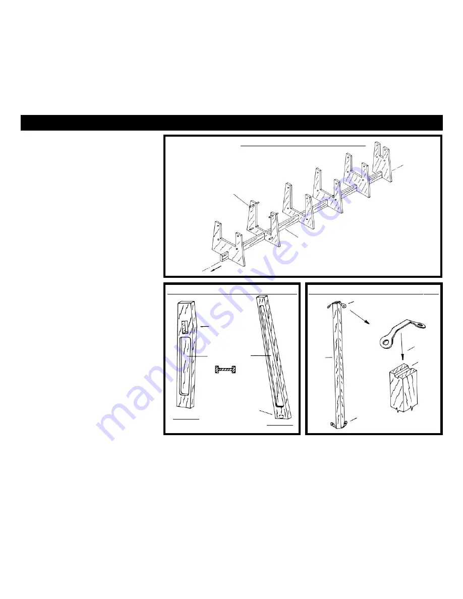
FIG. 3-1  FUSELAGE BUILDING JIG

F26 – CENTER PIECE

F27

TYPICAL 1/8"

DOWEL AT

EACH FORMER

F28

F29 – FORMERS

F30

F31

F32

FRONT

FIG. 3-3 STRUTS AT STATIONS 6 TO 11

1/16"
SQUARE

USE

SUPER

GLUE

FILE

GROOVE

F11

F11

top and bottom of the ribs like the stringers
of the wing ribs. These notches are not
laser-cut into the elevator ribs for fear the
rib may break between the upper and lower
notches before assembly.
After removing the elevator from the build-
ing board, add copper tape and the fittings
for the control cable brace wires (R2) at the
trailing edge in way of the ribs. Mount the
control horns (C2), then add the lower cap
strips to the ribs. Cut slots for the fake

hinges in the leading edge, then assemble
the elevator to the horizontal stabilizer using
brass strip as fake hinges.

Figure 2-4

illustrates the elevator assembly.

5. Mounting the Vertical Stabilizer

Now is a good time to mount the vertical 
stabilizer on top of the horizontal stabilizer.
Simply glue this on top of the center hori-
zontal stabilizer rib cap strip. Make sure it 
is vertical. On the real aircraft the vertical

stabilizer is bolted on.
You can install the brace wires at this time
using the 0.010" gray nylon cord. Short turn-
buckles (R3A) are located at the horizontal
stabilizer end.
Like the wings, store the completed tail sur-
faces and struts in a safe place until they are
ready to be installed on the fuselage.

FIG. 3-2 STRUTS AT STATIONS 3, 4 & 5

HOLE FOR 

ENGINE BEARER

SUPPORT BEAM

STATION 3

STATION 4

(5 SIMILAR)

HOLE FOR FAKE LOWER

WING HINGES – 

DRILL LATER TO 

MATCH WING

MORTISE BOTH

SIDES

Longerons – 1/16" x 3/32"
Engine support beam – 3/32" x 3/16"
Engine bearers – 1/8" x 3/16"
Longitudinal and transverse seat rails
and strut between rails – 1/16" x 1/8"
Floor board supports, large vertical struts
(Stations 4 & 5) and tailpost – 1/16" x 3/16"
Large vertical struts (Station 3) – 1/16" 
x 1/4"

Wood Dowels 

(cut to length as required)

Fuselage building jig dowel pins – 
1/8"-diameter

Rigging Cord 

(cut to length as required)

Fuselage cross bracing wires – 0.010"-
diameter gray nylon cord
Wrapping cord for splices – 0.008"-diam-
eter black nylon cord

1. Building the Fuselage Jig

The fuselage sides can be assembled directly
on the plan like the wings. Then, the sides
will be transferred to a building jig. The jig
will hold the sides in the correct shape so the
top and bottom struts can be added, result-
ing in a correctly shaped fuselage.
Start by assembling the laser-cut building
jig. Assemble the jig on a rigid board like a
plywood board or particle board (not sup-
plied in the kit). First, draw a straight guide
line on the board. Tack or glue (or both) the
jig center piece (F26) to the board, using the
drawn line to get it straight. Next, insert a
1/2" long piece of 1/8" dowel through each of
the round holes in all the laser-cut formers


Summary of Contents for CURTISS JN-4D JENNY

Page 1: ...o Inc Hollywood FL http www modelexpo online com PREPARED BY BEN LANKFORD Technical Characteristics SCALE 3 4 1 0 1 16 WINGSPAN 32 1 2 826 mm FUSELAGE LENGTH 20 1 2 521 mm I N S T R U C T I O N M A N...

Page 2: ...the pro duction models eliminated the lower wing ailerons Earlier aircraft used a wheel for controlling the rudder but the D model used sticks Quite a few Jenny s have been restored and are still fly...

Page 3: ...post 18 7 Installing the Front and Side Nose Plates and Engine Bearers 18 Stage 3 Building the Basic Fuselage continued 8 Installing the Cockpit Floor Board Supports and Floor Boards 19 9 Installing t...

Page 4: ...forma tion and a gallery of some fine WWI models on these pages The home page provides instructions for joining the mailing list if you are interested Thanks also to Ken Hyde from Warrenton VA an expe...

Page 5: ...table board is good for turning it around to make the work easier Working with the Plans Parts Before starting the model carefully exam ine the kit and study the plans First deter mine if all the list...

Page 6: ...nd sketches shown on Plan Sheet 1 Before starting each stage have all the parts required for the stage such as laser cut parts britannia castings photo etched parts stripwood rod and rigging identifie...

Page 7: ...1 16 Self Adhesive Copper Tape cut to shape as required Bands securing trailing edge to ribs and stiffeners Rigging Cord cut to length as required Drag wires in wings and kingpost wires 0 010 diameter...

Page 8: ...the stringer if the option is chosen to the shims use one of the full length lightened ribs to check the fit as you go The front end of the rib will butt against the leading edge and the bottom slots...

Page 9: ...the ailerons have the rod Position and glue the trailing edge to the ends of the ribs with just a touch of super glue Figure 1 8 After the wings are removed from the build ing board and the cap strip...

Page 10: ...to the remaining areas The cap strips butt into the ply sheet on top of the wing and to the lead ing edge on the bottom After the wings are removed from the build ing board add self adhesive copper ta...

Page 11: ...er the fittings have been installed or before drill a hole into the wing through the center hole of the fitting for receiving the wing strut kingpost and skid end fittings Figure 1 13 illustrates the...

Page 12: ...Drill a similar hole into the beams of upper wing center sec tion For the lower wing there will be holes drilled in the fuselage This will be shown in the fuselage building stage 15 Building and Inst...

Page 13: ...e wings For the model the casting is a solid fit ting with a pin extension This pin fits through the holes in the photo etched wing wire fit tings W22 and into the holes in the wings Shape the ends of...

Page 14: ...LIZER ASSEMBLY BRACE WIRE FITTINGS R1 1 32 X 1 16 DIAGONAL STIFFENER IS FLUSH WITH RIGHT SIDE OF STABILIZER TRAILING EDGE 1 16 X 1 16 CUT SLOTS TO FIT RUDDER FAKE HINGES LOCATE THIS STIFFENER ON CENTE...

Page 15: ...bottom prior to installing the ribs However be sure you extend the strips past the rear end of the ribs since the caps lie on the rabbeted trailing edge Cut the slots for the fake hinges in the trail...

Page 16: ...levator ribs for fear the rib may break between the upper and lower notches before assembly After removing the elevator from the build ing board add copper tape and the fittings for the control cable...

Page 17: ...des Cut these struts from stripwood For the model make the mortise using a hobby blade to cut the depth and a small chisel to hol low out the mortise Figure 3 2 The rear struts at Station 6 through 11...

Page 18: ...tail skid Figure 3 9 Between Stations 10 and 11 there are vertical diagonal boards which strengthen the fuse lage in way of the tail skid These fit on the inside of the longerons See the profile view...

Page 19: ...lled At this point these strips would hinder installing the flight controls on the floor boards 10 Installing Forward and Rear Cock pit Instrument Panels and Shelf Behind Rear Cockpit Firewall The rea...

Page 20: ...3 17 On the real aircraft these clips are actually a bolting clip for the struts For the model these are just fake clips for added detail The ends of the vertical struts at Station 2 through 5 requir...

Page 21: ...f the side strut clips that lay over the longerons at Station 6 to 10 The forwardmost former has a small access door probably a viewing port to the back of the fuselage Next install the stringers in t...

Page 22: ...N CORD DRILL HOLE FOR FITTING PIN FLOOR BOARDS IN COCKPIT Throttles Install a throttle E8 in both cockpits on the right longeron While you are at it add the throttle linkage to the engine It can be at...

Page 23: ...at we put off earlier The seat bottom is laser cut The back is photo etched alu minum Bend the back to the shape of the bottom and glue to the bottom There are some tabs on the aluminum back to be ben...

Page 24: ...e 1 of E10 Fuel tank cap 1 of E12 Fuel tank fuel gauge 1 of E13 Fuel tank sediment vial 1 of E14 Upper engine block 1 of E15A Upper engine block bolting feet 6 of E15B Lower engine block 1 of E16 Prop...

Page 25: ...lock is flat On the real engine these are a part of the upper block casting but for the model they have been cast separately Then glue the upper engine block assembly to the lower block Make sure the...

Page 26: ...n wiring below for other options Cylinder installation Figure 5 7 On real OX 5 engines some have cylinders which are secured in place with four steel rods through spider ends and some have no such hol...

Page 27: ...radiator but this will be installed after the engine is installed From the back of each pipe run a copper wire fake tubing from the pipe down to the top holes drilled in the sides of the V intake man...

Page 28: ...Then strap the dowels to the intake manifolds with strips of self adhesive copper tape Finally install the wiring using the flex ible wire provided First glue the wires to the top of the spark plugs...

Page 29: ...ator to the engine water pump Hang the pipe with a brass strap from the left engine bearer Connect the end of the pipe to the radiator with a short sec tion of PVC tubing Flex air heater tubing from t...

Page 30: ...rly straight prop Another popular prop had heavily curved ends This was a Paragon tractor prop manufacturer unknown made of six laminations of walnut or mahogany First insert a dowel through the cente...

Page 31: ...At the upper ends of the struts cut the struts to fit the fittings at the fuselage L7 and L8 and drill the holes for the castings pin extensions When done wrap the struts with black thread in the loca...

Page 32: ...e used to keep the parts cen tered Use a 3 32 wood dowel through the hub and tape or clamp the hub in the cen tered position as shown on the sketch First glue the half rim castings together and sit th...

Page 33: ...ument panel is almost FIG 7 1 INSTALLINGTHE COCKPIT COWL 010 CLEAR PLASTIC WINDSHIELD PATTERN IS ON PLAN FORMING THE COWL BEND GAP CLOSED BEND TABS UNDER AND UP ON INSIDE OF LONGERONS COPPER TAPE FAKE...

Page 34: ...llation Stage 4 Figure 4 3 Three back brace wires top and bottom for each of the elevator halves are fitted in a sim ilar manner The turnbuckles R3A short like the rudder are at the trailing edge The...

Page 35: ...ge holes at Stations 4 and 5 Place a temporary 3 32 thick wood strip at each end of the wing to gauge the gap between the fuselage and wing This gap is where the actual hinge pin is located on the rea...

Page 36: ...a real aircraft flying wires are tension wires to prevent the wings from folding up when flying Since these wires may have quite a bit of tension they are double wires The landing wires are the opposi...

Page 37: ...ol Wires See Figure 7 14 First rig the back brace wires for the aileron control horns Use the short turnbuckles R3A for these which are located at the trailing edge of the ailerons Start the control w...

Page 38: ...pril 1998 includes a plan of the OX 5 engine and Vol 152 May 1996 has excellent photos of a restoration with many details of the uncovered structure Jenny Was No Lady The Story of the JN 4Dby Jack R L...

Page 39: ...PHOTOS OF MODEL AIRWAYS JENNY 39...

Page 40: ...CTLY FROM OUR WEBSITE http www modelexpo online com NIEUPORT 28 1917 Model Airways Kit No MA1002 ALBATROS D VA Model Airways Kit No MA1001 1 16 Scale Open Framework Laser Cut Wood and Metal Kits Open...

Reviews: