13
are at the lower end at the wing and at top of
the kingpost for the fore and aft wires.
Note:
The kingposts are perpendicular to hori-
zontal and not at an angle like the wing struts.
17. Building the Upper Wing
Center Section
The center section is similar to the main
wing panels. The webs between the beam
flanges are the same thickness as the flanges.
The outer ribs are thicker than the center rib.
On the real aircraft these outer ribs are actu-
ally a box – two thin ribs with top and bottom
cap strips. Add the wire bracing fittings (R1)
to the webs of the beams. Rig the cords with
short turnbuckles (R3A).
Add the support pads and wing strut fittings
(W22) under the center section, and drill the
holes (if you have already not done so) for the
strut fittings as you did on the wings. Notice
that the upper and lower stringers on the cen-
ter section are staggered fore and aft. On the
main wing sections, the upper stringer is
directly above the lower stringer. Why this was
done on the actual aircraft is puzzling.
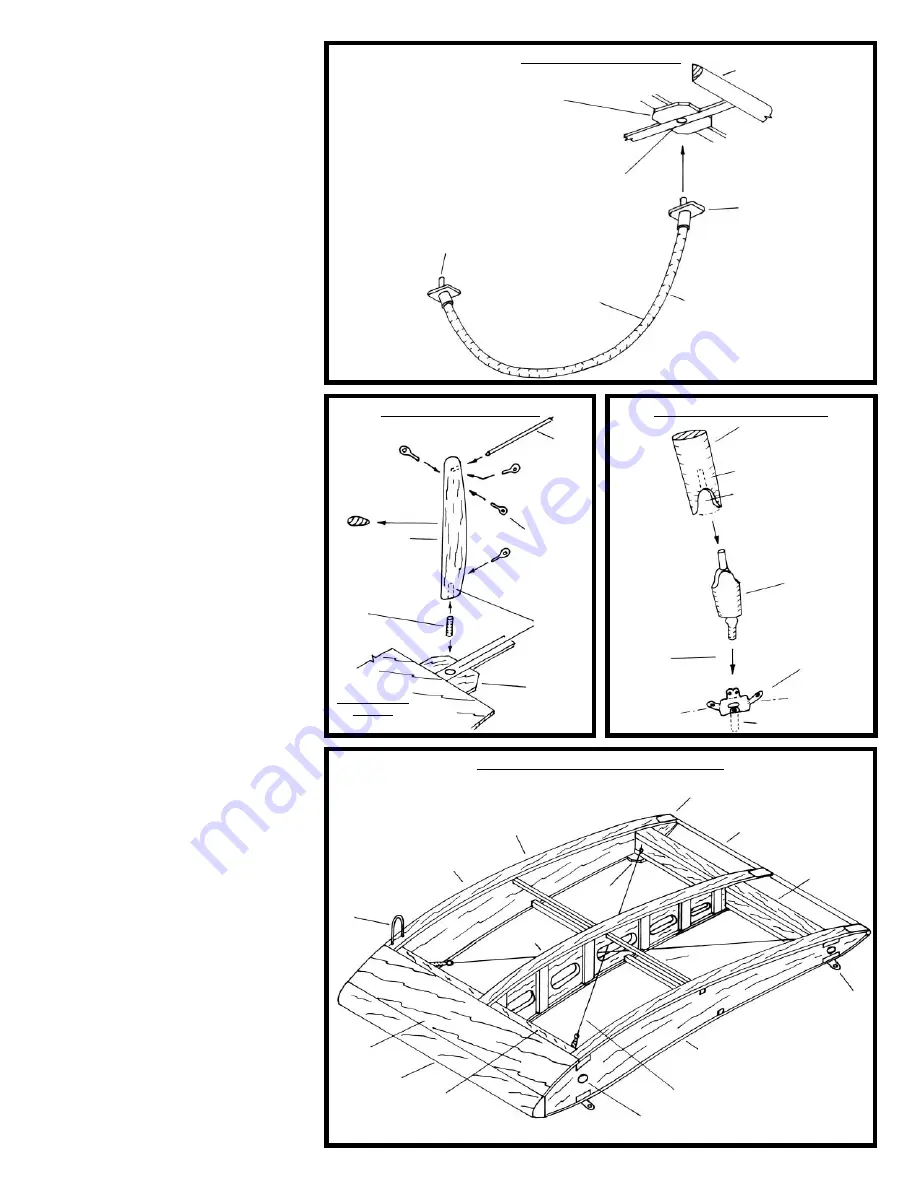
Figure
1-22
illustrates the completed center section.
18. Rounding the Leading Edge and
Wing Tips
If you haven’t gotten to it already, finish the
wings by rounding the leading edge and wing
tips. A sanding block should do the trick. See
the plan for the correct shapes.
19. Building the Wing Struts
The fittings at each end of the wing panel
struts and top of the center section struts are
britannia castings (W20). The fittings are oval
shaped, symmetrical in cross section front and
back, so the same casting can be used at the
upper and lower ends of the struts. However,
the laser-cut wood struts should be tapered in
between to a streamline, airfoil section as
shown on the plans. On the real aircraft the
end fittings are copper plate with a pin con-
nection that pins to the strut fittings on the
wings. For the model, the casting is a solid fit-
ting with a pin extension. This pin fits through
the holes in the photo-etched wing wire fit-
tings (W22) and into the holes in the wings.
Shape the ends of the wing struts to fit the
W20 end fittings and drill a hole for the cast-
ing pin extension into the strut. Epoxy the
fittings to the struts for added strength.
Don’t install the wing struts at this time, just
set aside for later.
Figure 1-21
illustrates the
wing strut construction.
The wings are now complete and can be
stained if desired and set aside. Store in a
protective cardboard box. Lay the wings flat
to help prevent warpage while stored. You
have two upper wing panels, an upper wing
center section, and two lower wing panels.
You also have all the wing struts completed
but not yet installed. The wings will be
assembled during the final stage. The struts
will be mounted, wings attached, rigging
wires added, and aileron, rudder, and elevator
control wires rigged.
FIG. 1-19 WING SKIDS
SUPPORT PADS UNDERSIDE
OF LOWER WING
AT FRONT BEAM
LEADING EDGE
STEAM OR WET
TO AID BENDING
IF NECESSARY
AT REAR BEAM SIMILAR
TO FRONT
DRILL 3/64" HOLE
SAND SKID ROUND 1/16"-DIA.
FROM 3/32" SQUARE
FLEXIBLE BEECH WOOD
CASTING W21
FIG. 1-20 KINGPOSTS
LASER-CUT
W19 – SAND
TO AIRFOIL
SHAPE
R1 RIG
FITTING
FRONT PANEL
SHOWN
(REAR SIMILAR)
SUPPORT
PAD – TOP
OF UPPER
WING
1/32"-DIA.
STEEL ROD
BETWEEN
FRONT
AND REAR
KINGPOSTS
DRILL
1/32"-DIA.
HOLE
1/32"-DIA.
BRASS
PIN
FIG. 1-22 WING CENTER SECTION
COPPER TAPE
CAP STRIP
W15
TRAILING EDGE
REAR BEAM –
WEB SAME
WIDTH AS
FLANGE
DRILL 1/16" HOLE FOR FAKE HINGE ROD
(SEE FIG. 1-18 FOR ROD)
W22 FITTING
UNDERSIDE
(SEE PLAN
DETAIL 2-J)
DRAG WIRES – TURNBUCKLES
R3A AT FRONT
BRASS ROD
FAIRLEAD
FOR AILERON
CONTROL
WIRE
(THIS SIDE
ONLY)
W15
FIG. 1-21 WING STRUTS
STRUTS WILL
BE INSTALLED
LATER
DRILL HOLE
FITTING W22
ON WINGS
CASTING
W20
LASER-CUT WING STRUT
W18 (LONG) OR
W17 (SHORT)
CUT TO FIT W20
HOLE IN WING BEAM
COVER
PLY
LEADING
EDGE
FRONT BEAM –
WEB SAME WIDTH
AS FLANGE
SUPPORT
PAD
W16
STRINGERS


