MMP SA-2550A
Page 12 of
24
Midwest Motion Products
DESIGN, MANUFACTURING & DISTRIBUTION - MOTION CONTROL EQUIPMENT
email:
How to reverse a brushless DC motor
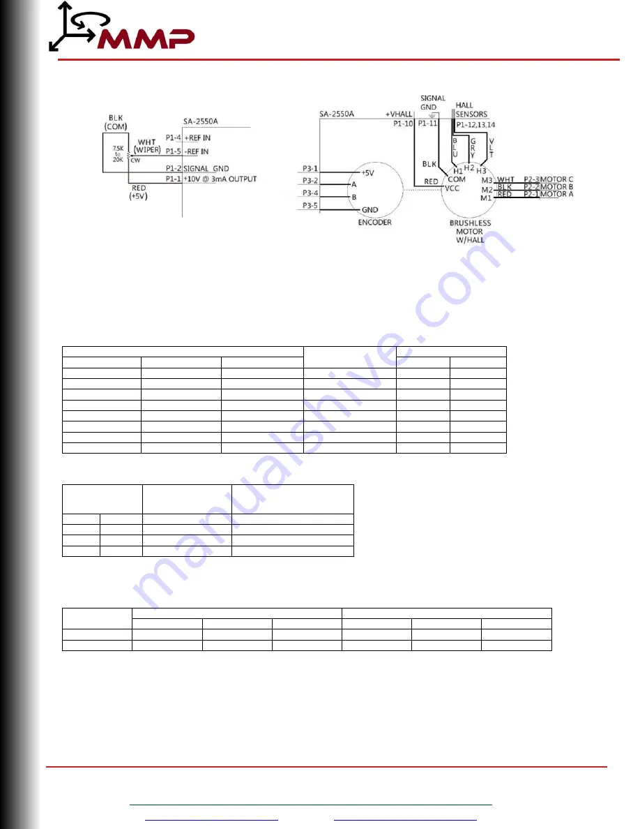
Figure 2. Typical Wiring Solution of a Brushless Motor with Encoder.
The typical wiring solution shown above results in the brushless motor to run forward (CW rotation) with the potentiometer max at
the CW position. Methods to reverse the brushless motor direction via wiring are as follows:
-
Change the wiring connections of the potentiometer or jump leads. There are many ways to wire a potentiometer to the
servo amplifier or jump the potentiometer leads. Consult the tables below for what leads to connect to which pins.
Potentiometer Wiring Solutions
Connect Potentiometer Leads to Pins
Motor Direction
of Rotation*
Potentiometer
RED (+5V)
BLK (GND)
WHT (WIPER)
Range
Rotation
P1-1
P1-2
P1-5
FWD
0-100%
CW
P1-3
P1-2
P1-4
FWD
0-100%
CW
P1-1
P1-2
P1-4
REV
0-100%
CW
P1-3
P1-2
P1-5
REV
0-100%
CW
P1-2
P1-3
P1-4
FWD
100-0%
CCW
P1-2
P1-1
P1-5
FWD
100-0%
CCW
P1-2
P1-1
P1-4
REV
100-0%
CCW
P1-2
P1-3
P1-5
REV
100-0%
CCW
*Assumes that Hall Sensors and Motor Leads are wired in accordance with the above diagram.
Wire without Potentiometer (direct pin connections)
Connect Leads
Motor Direction
of Rotation*
Simulated
Potentiometer Output
P1-1
P1-5
FWD
100%
P1-3
P1-4
FWD
100%
P1-1
P1-4
REV
100%
P1-3
P1-5
REV
100%
*Assumes that Hall Sensors and Motor Leads are wired in accordance with the above diagram.
-
Change Motor and Hall Sensor Leads. To reverse motor direction, consult the below table to properly change motor and hall
sensor leads.
Motor
Direction
Hall Sensor Connection to Drive
Motor Connection to Drive
H1 (BLU)
H2 (GRY)
H3 (VLT)
M1 (RED)
M2 (BLK)
M3 (WHT)
FWD
P1-12
P1-13
P1-14
P2-1
P2-2
P2-3
REV
P1-14
P1-13
P1-12
P2-2
P2-1
P2-3
WARNING : DO NOT reverse the servo amplifier input power leads, HV (P2-5) and GND (P2-4) to reverse the direction of motor
rotation. This can cause severe, irreversible damage to the servo amplifier.
MIDWEST M
O
TION
P
RODUCTS


