background image

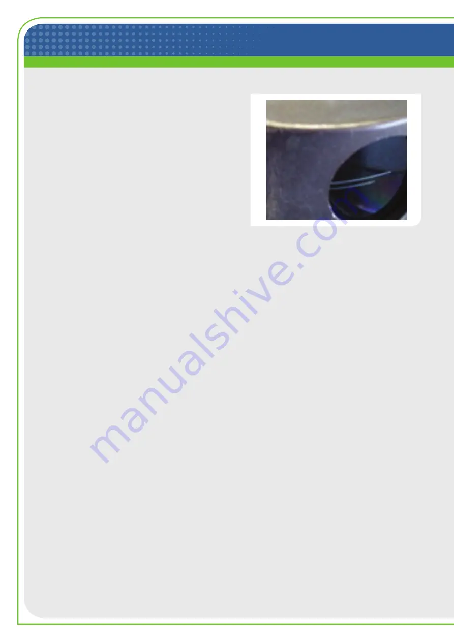
Power Window damage (Laser) 

Damage to the power window can occur at levels 
below the damage threshold for the slit aperture, 
specifically for the P75 Wratten Filter option, which has 
been discontinued as a product offering.

detector damage (Laser) 

Detectors can be damaged if the slit aperture is cut or 
burned through and the detector is directly exposed. 
This damage is avoided by adhering to the guidelines 
for slit protection.

circuit and encoder damage (Laser)


Failure of the NanoScan circuitry and the optical 
encoder can occur when the scanhead is exposed to 
high average power which causes the entire scanhead 
to heat. For example, exposure to 180Watts for only a 
minute or so can heat the drum to temperatures that 
cause warping of the encoder disc and catastrophic 
failure. This type of damage is avoided by using only 
short exposure times depending on the laser average 
power level. Safe operating time depends on the power 
as well as the slit material and laser wavelength. Table 4 
gives safe operating times for different conditions.

Motor damage (Mechanical)


Typically motor damage is due to dropping the scanhead, 
which results in a bent motor shaft and consequent 
catastrophic failure. This type of damage can also occur 
during shipping if the scanhead is not packaged properly. 
To avoid this type of damage, do not drop the scanhead, 
and use at least 2” of rigid foam material or equivalent 
packaging if the system is shipped. 

cable (Mechanical)


The signal cable can be damaged due to bending the 
cable to too tight a radius, or from repetitive bending 
when the scanhead undergoes repetitive motion.

cable (Laser)


The cable can be severed by a high power laser when 
accidentally exposed to high power/energy lasers. This 
type of damage is avoided by careful routing of the cable.

out of tolerance conditions


Out-of-tolerance conditions are of two main types: either 
system related or use related.

Operation related problems are due to using a scanhead 
that is inappropriate for the specific application. 
Examples include using a Silicon detector to measure 
a 1550nm source, measuring a 10µm spot with a 25µm 
slit, or measuring 100µm spot at 1064nm with a Si 
detector. These conditions are remedied by the use of 
the proper scanhead, which should have been the one 
specified at the time of purchase. However, many times 
scanheads are then used in other situations, and that is 
where problems can arise.

System related problems include items such as 
ScanHead EEPROM Communication, Motor Quiescent 
Voltage, Motor Speed, and Baseline Offset Voltage. 
System related conditions are diagnosed in the software 
during system startup, and if encountered the system 
will not start and an error message is displayed. There 
is nothing that can be done for these conditions except 
returning the system for calibration.

need additional Help?


Here at Ophir-Spiricon we are committed to the 
satisfaction of our customers. If you would like to speak 
to a representative about any information contained in 
this article, about new products, or to optimize your laser 
measurement system for accurate, consistent, and highly 
repeatable results, please do not hesitate to contact us.

Power Window Damage 

Summary of Contents for Ophir nanoScan

Page 1: ...am profiler are due to either scanhead damage or out of tolerance conditions Scanhead damage can be categorized into two main types Laser and Mechanical Laser damage is the most prevalent and results from exposure to lasers with excessive laser power energy density and or high average power The damage can be classified into 2 categories designated Instantaneous and Long Term ...

Page 2: ...culate environments and repetitive motion Mechanical damage includes bent motor shafts distorted slits plugged slits and broken signal cables Out of tolerance conditions are either system related including problems associated with circuit or motor failure or the scanhead is not appropriate for the application such as using a Silicon detector to measure a 1550nm source or a 25µm slit for a 10µm bea...

Page 3: ...e damaged if stopped in the beam and if this occurs the detector may also be damaged Use of a beam dump is recommended until the drum is spinning When running long term tests with NanoScan Configure the PC Power Management to NEVER go off and to NOT ALLOW Automatic Updates These cause the computer to reboot closing the NanoScan program and stopping the NanoScan drum potentially subjecting it to th...

Page 4: ...ing on the application and measurement configuration while contamination by many particles is more likely to create a problem With pinhole apertures a single particle can be disastrous Therefore when the system is not is use it is recommended that the protective plastic cap be used to cover the scanhead entrance aperture to avoid possible contamination If inconsistent performance is observed and c...

Page 5: ... of visual damage occurs The average irradiance is defined as the average power divided by the beam area at the 1 e beam diameter All tests were performed under normal NanoScan operating conditions with the aperture slits moving Damage to the slit apertures can occur at much lower power levels if the laser beam is directed into the slit apertures while the apertures are stationary The tests were p...

Page 6: ...l scanheads Fluence exposure thresholds for pulsed lasers are given in Table 2 for nickel alloy blackened nickel alloy and copper slit apertures Table 1 Recommended maximum average laser irradiance incident on blackened and unblackened Nickel NanoScan slit apertures for short time exposures Aperture Slit µm Visual Damage Threshold W cm2 355nm 532nm 1064nm 10 6µm Unblackened 1 2 2x10⁵ 3x10⁵ 1x10⁶ N...

Page 7: ...or the time limit because it neglects thermal conduction into the drum For reported times 5minutes it is generally safe to operate with continuous exposure but caution is advised Exposure time limits for nickel alloy and copper slit apertures are given in Table 3 Long Term Drum Heating Exposure Limits The long term exposure limits for drum heating are based on a heating model where all the laser p...

Page 8: ...ue to bending the cable to too tight a radius or from repetitive bending when the scanhead undergoes repetitive motion Cable Laser The cable can be severed by a high power laser when accidentally exposed to high power energy lasers This type of damage is avoided by careful routing of the cable Out of Tolerance Conditions Out of tolerance conditions are of two main types either system related or us...

Page 9: ...red Software Solutions BeamGage Standard BeamGage Professional Dual or Single Monitor Set Up M Measuring System Medical Military Industrial Processes Scientific Research Applications Scanning Slit Camera products for almost any wavelength from 13nm 3 000µm ...

Page 10: ... Viton is a registered trademark of E I Dupont Wilmington DE www ophiropt com 2020 MKS Instruments Inc Specifications are subject to change without notice Ophir Spiricon LLC Calibration Team 3050 North 300 West North Logan UT 84341 Phone 435 753 3729 E mail service ophir usa mksinst com For latest version please visit our website www ophiropt com photonics Copyright 2020 Ophir Spiricon LLC N Logan...

Reviews: