MKS 943 Series Instruction Manual Download Page 40

Service & Maintenance

40

Series 943 Cold Cathode Vacuum Sensor

Instruction Manual - #100009887

6.5.3  Reassemble the Sensor

1.

Check the anode (8). It should be straight and centered with the sensor body (7) for proper 
operation.

2.

Roll the sensor body on a flat surface and look for any radial run out motion.

3.

Install the ground shield 6 using tweezers. Make sure that at the groove of its larger diameter, 
the ground shield interlocks with the locating collar 11.

4.

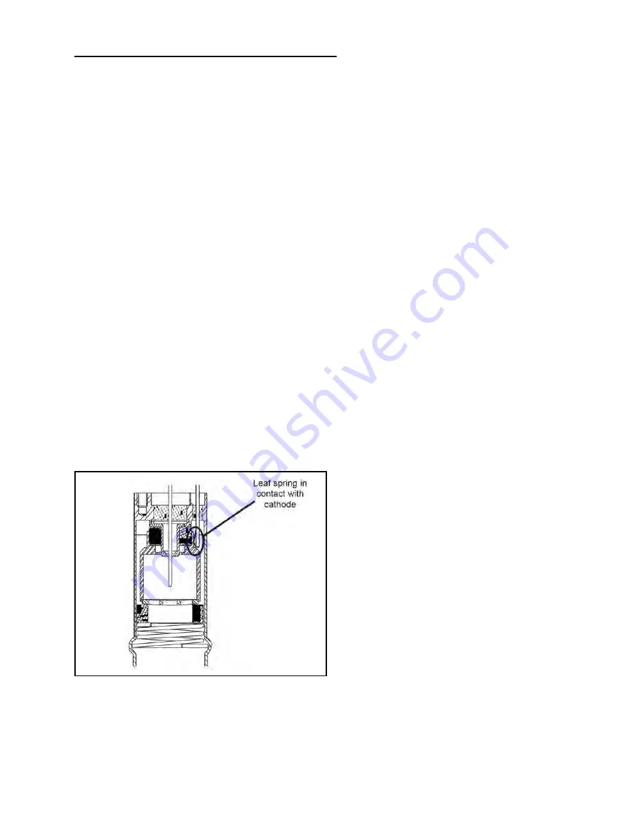
Slide the small ceramic spacer 5 over the small end of the ground shield 6. Check that the leaf 
spring 9 will contact the base of the cathode 4 as shown to the right. If not, remove the small 
ceramic spacer and the ground shield. Gently bend the leaf spring towards the anode and 
ceramic spacer.

5.

Slide the cathode 4, the grid washer 3, and the large ceramic spacer 2 into place. The grid 
washer has a concave shape. Refer to the figure to see its installation orientation.

6.

Insert the small end of the compression spring 1 into the sensor body 7. Using your thumbs, 
push the larger end of the spring into the sensor body until it is contained within the tube's 
inside diameter. Using the smooth-jaw, needle-nose pliers, work the compression spring down 
into the sensor body until it is fully seated in the formed groove.

7.

Inspect the ground shield 6 and the grid washer 3 to verify they are centered with respect to 
the anode 8. If adjustment is needed, gently reposition the grid washer/cathode assembly, 
taking care not to scratch the grid washer.

8.

Measure the resistance between the ion current feed through pin 13 and the grid washer 3 to 
verify that the leaf spring 9 is in contact with the cathode 4. The measurement should indicate 
a short circuit between them. There should be an open circuit between the ion current feed 
through pin 13 and both the high voltage feed through pin 10 and sensor body 7.

9.

The Sensor is ready for installation. If it is not immediately installed, cover the flange with a 
clean vacuum grade cap / flange protector.

Figure 6-2: Proper Installation of Leaf Spring and Cathode (Step 8)

Summary of Contents for 943 Series

Page 1: ...Cold Cathode Vacuum Sensor System Instruction manual part number 100009887 Revision D May 2020 Series 943 Instruction Manual ...

Page 2: ......

Page 3: ...pective owners Instruction Manual Series 943 This instruction manual is for use with Series 943 Cold Cathode Vacuum Sensor System A list of applicable catalog numbers is provided on the following page Cold Cathode Vacuum Sensor System Customer Service Technical Support MKS Global Headquarters 2 Tech Drive Suite 201 Andover MA 01810 USA Phone 1 833 986 1686 Email insidesales mksinst com Visit our w...

Page 4: ...r System 943 A 120V50 PA PC 943 A 120V50 TR NA 943 A 120V50 TR PC 943 A 120V60 PA PC 943 A 120V60 TR PC 943 A 120V60 TR PC 01 943 A 120V60 TR PC 02 943 A 120V60 TR NA 943 A 220V50 PA PC 943 A 220V50 TR NA 943 A 220V50 TR PC 943 A 220V60 PA PC 943 A 220V60 TR NA 943 A 220V60 TR PC 943 A 220V60 PA PC 02 ...

Page 5: ...alog Output 21 4 1 7 Remote High Voltage Enable Disable 23 4 1 8 Relay Inductive Loads and Arc Suppression 24 4 2 Installing a Series 943 System Sensor 25 4 2 1 Locating a Cold Cathode Sensor 25 4 2 2 Orienting a Cold Cathode Sensor 25 4 2 3 Managing Contamination in a Cold Cathode Sensor 25 4 2 4 Testing a Cold Cathode Sensor 25 4 2 5 Connecting a Cold Cathode Sensor 25 Chapter 5 Operation 27 5 1...

Page 6: ...on Manual 100009887 6 4 Troubleshooting 37 6 5 Contaminated 943 Sensor 38 6 5 1 Disassembly 39 6 5 2 Cleaning the Components 39 6 5 3 Reassemble the Sensor 40 6 6 Customer Service Technical Support 41 6 7 Accessories Spare Parts 42 Chapter 7 Index 43 ...

Page 7: ...arder or airline making delivery to the customs broker must be notified within 15 days of delivery The following illustrates to whom the claim is to be directed If an airfreight forwarder handles the shipment and their agent delivers the shipment to customs the claim must be filed with the airfreight forwarder If an airfreight forwarder delivers the shipment to a specific airline and the airline d...

Page 8: ...n products without first obtaining an RMA In some cases a hazardous materials disclosure form may be required The MKS Customer Service Representative will advise you if the hazardous materials document is required When returning products to MKS be sure to package the products to prevent shipping damage Shipping damage on returned products as a result of inadequate packaging is the Buyer s responsi...

Page 9: ...tes a hazardous situation which if not avoided will result in death or serious injury Warning indicates a hazardous situation which if not avoided could result in death or serious injury Caution indicates a hazardous situation or unsafe practice which if not avoided may result in minor or moderate personal injury Indicates a situation or unsafe practice which if not avoided may result in equipment...

Page 10: ...t local regulations Operation and Service of this equipment in strict accordance with the methods and procedures supplied by MKS is the responsibility of the Customer MKS assumes no liability whatsoever for any personal injuries or damages resulting from the operation or service of this equipment in any manner inconsistent or contrary to the methods supplied in MKS literature including but not lim...

Page 11: ...vide sufficient electrical conduction via a plasma to couple a high voltage electrode potential to the vacuum chamber If exposed conductive parts of the gauge controller and chamber are not properly grounded they may attain a potential near that of the high voltage electrode during this coupling Potential fatal electrical shock could then occur because of the high voltage between these exposed con...

Page 12: ...oltage All conductors in on or around the vacuum system that are exposed to potential high voltage electrical discharges must either be shielded at all times to protect personnel or must be connected to Earth ground at all times High Voltage Be aware that an electrical discharge through a gas may couple dangerous high voltage directly to an ungrounded conductor almost as effectively as would a cop...

Page 13: ... that these safety devices are properly installed before installing and operating the product Ensure the following precautions are complied with at all times 1 the proper gas cylinders are installed 2 the gas cylinder valve positions are correct on manual systems 3 and the automation is correct on automated gas delivery systems Explosive Environment Do not use the Series 943 Vacuum Sensor System i...

Page 14: ... has been dropped or the enclosure has been damaged f When the product exhibits a distinct change in performance This indicates a need for service See Service Guidelines Section 1 5 for detailed information regarding how to contact MKS Customer Service Representatives Vacuum gauges with compression fittings may be forcefully ejected if the vacuum system is pressurized Notice Do not substitute part...

Page 15: ...ures Measurement of high vacuum chamber pressures Control of high vacuum systems and process sequencing using relay set points Sensing abnormal pressure and taking appropriate security measures using relay set points Controlling system pressure using analog output as input to an automatic pressure controller Starting or stopping system processes with relay set points Measuring pressures of backfil...

Page 16: ...or 24 Vdc Relay Response 50 msec for pressures 10 8 Torr Case Material Aluminum anodized Materials exposed to vacuum 304 stainless steel platinum glass nickel Weight with CF Flange 2 3 lb 1 04 kg Insulation Coordination Installation Overvoltage Category II Pollution Degree 2 Dimensions W x D x H 3 x 7 x 3 96 mm x 178 mm x 96 mm Size 1 4 DIN Typical Weight with KF Flange 2 2 lb 1 kg Altitude 2000 m...

Page 17: ...ontroller or Cables Series 421 250 C 482 F when backshell subassembly removed 125 C 257 F Series 423 500 C 932 F for CF flange model magnet removed Diameter Series 421 2 2 in 56 mm Series 423 2 6 in 66 mm Length Series 421 6 3 in 160 mm Series 423 3 4 in 86 mm Typical Weight with 2 CF Flange 421 2 4 lb 1 1 kg 423 1 8 lb 0 8 kg Vacuum Connection KF 25 KF 40 2 CF 423 rotatable 8 VCR F 1 tubing Speci...

Page 18: ...3 Specifications 18 Series 943 Cold Cathode Vacuum Sensor Instruction Manual 100009887 Notes ...

Page 19: ... the thumbscrews provided Figure 4 1 1 4 DIN Panel Mount Adhesive backed rubber feet for benchtop use are also included in the mounting kit 1 Remove the adhesive backing from each foot 2 Apply one to each corner of the aluminum bottom surface 4 1 1 AC Power Cord The Series 943 Controller may be ordered with a North American standard 120 VAC 50 60 Hz power cord with a female IEC 320 connector If th...

Page 20: ...emote disabling can be accessed from the Accessory port on the rear panel of the Controller A connector kit to mate to the port is provided The figure and chart below identify the pin functions of the Accessory connector Do not exceed the rated line voltage of your unit Electrical shock may result Table 4 1 15 Pin D sub Accessory Connector Pin Function 1 Set point relay 1 normally closed contact 2...

Page 21: ...10 6 Torr This output is provided by a microcontroller driving a D A converter and has a response time of about 0 25 sec 4 1 6 Buffered Analog Output A pressure dependent voltage V0 with a range of 0 to 9 V is provided on pins 13 and 14 Pressure can be determined using the graph shown in Figure 4 2 or Figure 4 3 This output is simply a buffered output of the sensor circuit and has a fast response ...

Page 22: ...4 Installation 22 Series 943 Cold Cathode Vacuum Sensor Instruction Manual 100009887 Figure 4 2 Cold Cathode Analog Output Voltage vs Pressure ...

Page 23: ... voltage may be turned OFF or ON using a set point from a low vacuum sensor such as a Pirani or convection Pirani Use pins 9 and 10 to connect the Controller to the sensor for this external control To use this input toggle the high voltage switch to Remote If the high voltage is disabled by the protect set point the Remote connection must be set to first disable and then enable the high voltage to...

Page 24: ...see Figure 4 4 is recommended The values of the capacitance C and the resistance R are calculated by the equations where a 1 50 E C is in microfarads R is in ohms I is DC or ACpeak load current in amperes E is DC or ACpeak source voltage in volts Note that Cmin 0 001 mF and Rmin 0 5 W Figure 4 4 Relay Arc Suppression Network Table 4 3 Remote High Voltage Enable Disable If Pin 9 is High voltage is ...

Page 25: ...ling into it 4 2 3 Managing Contamination in a Cold Cathode Sensor If pressure readings appear to be erratic the Sensor may be contaminated Inspect it visually If contamination is visible e g discoloration of the aluminum cathode replace the internal components with an Internal Rebuild Kit see Section 6 7 Accessories Depending on the degree of contamination and application of the Sensor the intern...

Page 26: ...ctor and Ion Current SMA connector Where stress might be applied to the cable use separate strain relief to avoid damage to the sensor cable or the Controller Cables are available from the factory in standard lengths of 10 25 50 and 100 feet and in custom lengths up to 300 ft Some applications may require the use of special cables such as where the connection must be routed through restrictive bar...

Page 27: ...o filament to break or burn out which makes it immune to inrushes of air and it is relatively insensitive to vibration damage No x ray limit for lower pressure measurement No adjustment for emission current or filament voltage is needed Degassing is not needed Properly designed sensor tubes can be cleaned and reused almost indefinitely With only one current loop the control circuit is simple and q...

Page 28: ... transit between the electrodes and the discharge soon builds up to a stable value Start of the discharge normally requires a very short time at 10 6 Torr or above a few minutes at 10 8 Torr and longer times at lower pressures At high pressures the current increases and sputtering of the cathode can become a problem A large series resistor reduces sputtering and the voltage across the tube is pres...

Page 29: ...e operate the set point relays and supply analog voltage vs pressure outputs See Figure 5 1 5 3 1 High Voltage Power Supply The high voltage power supply is a DC to DC voltage converter This circuit requires very few components which ensures high reliability and is closed loop controlled to a reference voltage to provide a very stable high voltage output The high voltage output is connected to the...

Page 30: ...e result to produce a pressure dependent voltage signal This voltage drives the A D converter unprocessed analog output and the set point relay circuitry 5 3 4 Set Point Comparators This part of the circuit compares the output of the signal processing circuitry to the value of the set point adjusting potentiometers and turns the process control relays on and off accordingly 5 3 5 Microprocessor Th...

Page 31: ...er Support at phone 1 833 986 1686 or email insidesales mksinst com In a cold cathode ionization sensor the degree of ionization hence the indicated pressure is gas type dependent see Section 5 1 The 943 System provides analog voltage output for air or nitrogen according to Figure 5 4 and Figure 5 5 If used with another gas the Controller displays nitrogen equivalent pressure a pressure correspond...

Page 32: ... requires a gas independent sensor such as a capacitance manometer or a spinning rotor gauge to act as the calibration standard A curve can then be generated The Series 943 Controller cannot be calibrated for direct pressure readings of gases other than air or nitrogen The calibration is intended only to match the air nitrogen curve of the sensor Gas type dependence can either be an advantage or a...

Page 33: ...pears on the Controller display Operating the sensor at pressures above 10 2 Torr will not only give an incorrect reading but may also damage the sensor see Section 5 6 2 5 6 Set Points 5 6 1 Adjusting the Set Points To adjust a set point to open or close its relay contact at a particular pressure 1 Depress and hold the View Set Point push button on the front panel for Set Point 1 or 2 2 Use a sma...

Page 34: ... the reading coincides with the desired set point pressure If the protect set point turns the high voltage OFF PRO will appear on the display Turn OFF the high voltage switch and then back ON again to enable the high voltage The protect set point cannot work if the system s pressure is in the sensor s roll back pressure region see Figure 5 4 ...

Page 35: ... static sensitive devices or other components removed from the product Do not handle static sensitive devices more than absolutely necessary and only when wearing a ground strap Do not use an ohmmeter for troubleshooting MOS circuits Rely on voltage measurements Use a grounded electrostatic discharge safe soldering iron NOTE This product is designed and tested to offer reasonably safe service prov...

Page 36: ...d or the enclosure has been damaged The product exhibits a distinct change in performance This may indicate a need for service Product Modifications Do not substitute parts or modify the instrument Because of the danger of introducing additional hazards do not install substitute parts or perform any unauthorized modification to the product Return the product to a service facility designated by MKS...

Page 37: ...e 1 Plug into functional AC outlet with the correct voltage 2 T urn power ON 3 Replace fuse 4 Return to MKS for repair LO is displayed 1 Ion current or high voltage cable may be disconnected or may have a bad or broken connection 2 Sensor discharge may not have yet started 3 Pressure may be below 4 System s range 5 Pressure may be above System s range 1 Check cable connections Replace cable if nec...

Page 38: ... be contaminated Inspect it visually If contamination is visible you should replace the internal components with an Internal Rebuild Kit see Section 6 7 Accessories Depending on the degree of contamination and application of the sensor the internal parts may be cleaned either ultrasonically with mild abrasives or chemically Figure 6 1 943 Cold Cathode Sensor Assembly Illustration ...

Page 39: ...uch as ALCONOX 2 Scrubbing with mild abrasives can remove most contamination 3 Scotch Brite or a fine emery cloth may be effective Rinse with alcohol 4 Clean aluminum and ceramic parts chemically in a wash such as a 5 to 5 20 sodium hydroxide solution not for semiconductor processing at room temperature 20 C for one minute Follow with a preliminary rinse of deionized water Remove the black residue...

Page 40: ...sert the small end of the compression spring 1 into the sensor body 7 Using your thumbs push the larger end of the spring into the sensor body until it is contained within the tube s inside diameter Using the smooth jaw needle nose pliers work the compression spring down into the sensor body until it is fully seated in the formed groove 7 Inspect the ground shield 6 and the grid washer 3 to verify...

Page 41: ...n products without first obtaining an RMA In some cases a hazardous materials disclosure form may be required The MKS Customer Service Representative will advise you if the hazardous materials document is required When returning products to MKS be sure to package the products to prevent shipping damage Shipping damage on returned products as a result of inadequate packaging is the Buyer s responsi...

Page 42: ...3 Cold Cathode Sensor Series 423 Cold Cathode Sensor 2 ft 3 0 m 100002505 KF 25 104230004 25 ft 7 6 m 100007873 KF 40 104230001 50 ft 15 2m 100007874 2 3 4 CF 104230002 100 ft 30 5 m 100002395 1 tube 104230003 Custom to 300 ft 91 4 m 100008759 Internal Rebuild Kit for Series 421 Sensor IgniTorrTM Cold Cathode Sensor Starting Device for use with CF flange only Cathode Washer Copper Gasket Abrasive ...

Page 43: ...eral Description 15 Improper Use 15 Intended Use 15 O Over Pressure Conditions 13 R Receiving Inspection 7 S Safety Cautions Warnings 9 10 Service 14 Contact Information 41 Guidelines 8 41 Service guidelines 35 Specifications 16 Storage 15 W Warning Notices Symbols 9 10 Warranty 7 Series 943 Cold Cathode Vacuum Sensor Index Instruction Manual 100009887 ...

Page 44: ...Series 943 Cold Cathode Vacuum Sensor Instruction Manual 100009887 ...

Page 45: ... ...

Page 46: ...020 Series 943 Instruction Manual Cold Cathode Vacuum Sensor System Customer Service Technical Support MKS Global Headquarters 2 Tech Drive Suite 201 Andover MA 01810 USA Phone 1 833 986 1686 Email insidesales mksinst com Visit our website at www mksinst com ...

Reviews: