5 - 3
5. PARAMETERS
The following parameters are those added to or modified in the MR-J2S- B-S096.
For other parameters, refer to the MELSERVO-J2S-B Instruction Manual as they are the same as those
of the standard model.
Class No. Abbreviation
Name
Initial Value
Unit
Setting
Range
Ba
si
c pa
ra
m
ete
rs
01
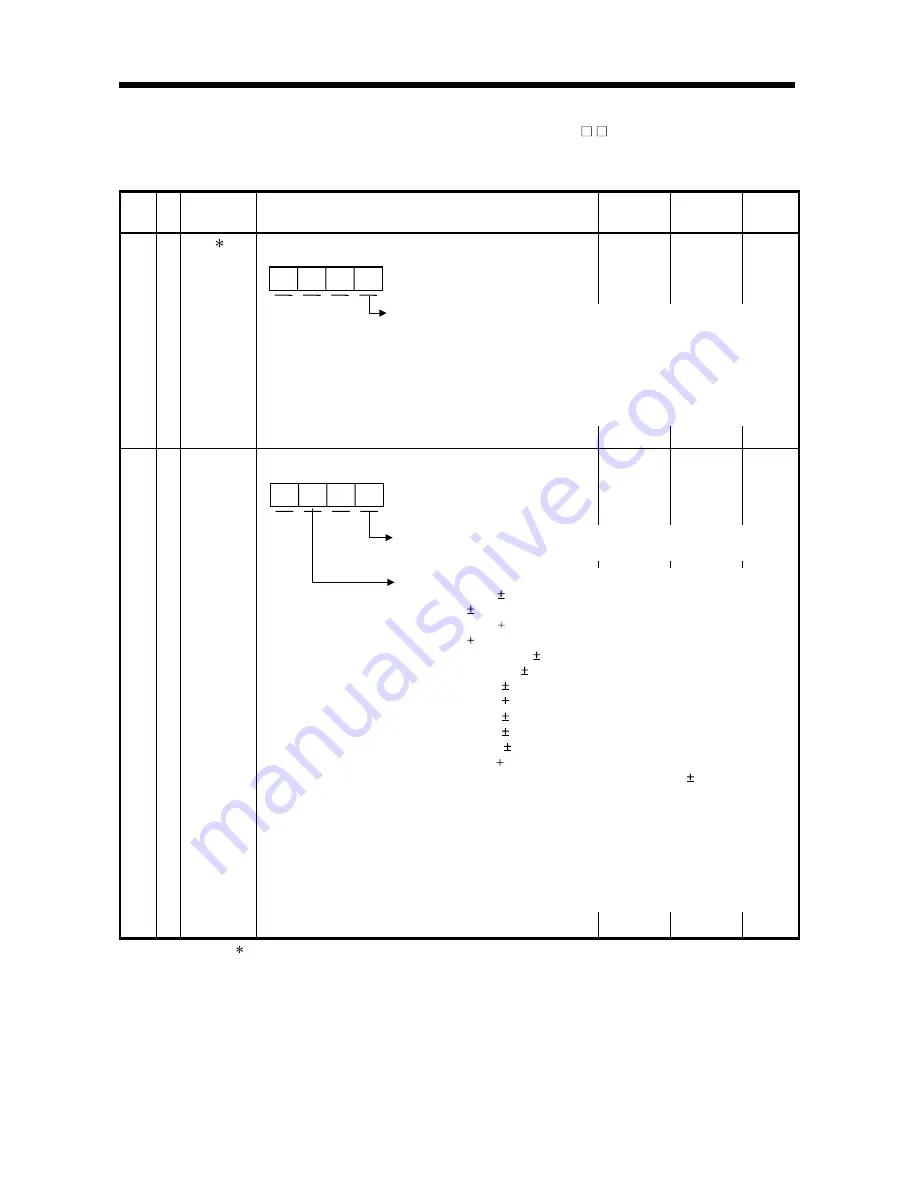
AMS Amplifier setting
Select the amplifier setting.
0000
0000h
to
0001h
Adjus
tm
ent pa
ra
m
ete
r
22
MOD Analog monitor output
Set the signals output to the analog monitor outputs.
0001
0000h
to
4C4Ch
The parameter marked is valid only at power-on.
Absolute position detection selection
0: Invalid (used in incremental system)
1: Valid (used in absolute position detection system)
Note: The INC type linear scale is compatible with the incremental
system only. It is also compatible with the incremental system
only when "2: Switching valid" is selected for the full closed
function. If absolute position detection valid is selected in
such cases, the parameter error AL-37 occurs.
Analog monitor ch2 output selection
The settings and their definitions are as in analog monitor ch1.
Analog monitor ch1 output selection
0: Motor speed ( 8V/maximum speed)
1: Torque ( 8V/maximum torque)
2: Motor speed ( 8V/maximum speed)
3: Torque ( 8V/maximum torque)
4: Current command ( 8V/maximum current command)
5: Speed command ( 8V/maximum speed)
6: Droop pulses ( 10V/128 pulses)
7: Droop pulses ( 10V/2048 pulses)
8: Droop pulses ( 10V/8192 pulses)
9: Droop pulses ( 10V/32768 pulses)
A: Droop pulses ( 10V/131072 pulses)
B: Bus voltage ( 8V/400V)
C: Motor end full closed end position difference ( 10V/131072
pulses)
Droop pulses are in the pulse unit of the motor end.
The difference between the position command and linear
scale is output.
By setting parameter No. 68 "droop pulse unit selection",
droop pulses can be output in the full closed end pulse unit.
Summary of Contents for Melservo-J2-SUPER series
Page 19: ...1 6 1 FUNCTIONS AND CONFIGURATION MEMO...
Page 49: ...2 30 2 LINEAR SCALES MEMO...
Page 85: ...5 8 5 PARAMETERS MEMO...


