2 - 23
2. LINEAR SCALES
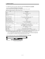
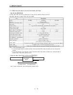
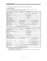
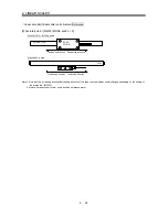
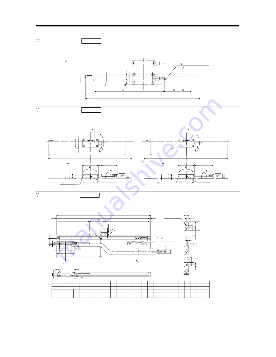
SL710 outline drawing Reference
(Dimension unit: mm)
This outline drawing is based on the data from Sony Precision Technology. Contact Sony Precision
Technology for this outline drawing.
SL710
Mount the scale on a non-magnetic material.
When mounting it on a magnetic material, provide
a non-magnetic layer of 3mm or more.
n - D reamed hole
(For D parallel pin insertion)
P (n - 1 or 2)
Effective measurement length (ML)
Full length = effective measurement 40
(20)
20
D/2
P 200
12
0
.05
25
9
ML - P (n - 1) 200
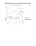
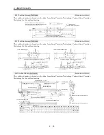
PL101 outline drawing Reference
(Dimension unit: mm)
This outline drawing is based on the data from Sony Precision Technology. Contact Sony Precision
Technology for this outline drawing.
<PL101-RH (IP67 type)>
Offs
et
Effective measurement length (ML)
Full length = effective measurement 40
Cl
e
ar
a
nc
e
2 2 - M3 depth 5
43.5
Pitch
Roll
Cable length: 3000mm
48
Center mark
<PL101-N/PL101-R (IP50 type)>
Offs
et
Effective measurement length (ML)
Full length = effective measurement 40
Cable length: 3000mm
Roll
Pitch
Center mark
43.5
2 2 - M3 depth 5
11.5
48
1.5
0.
1
5
12
6
0.
1
5
Cl
e
ar
a
nc
e
12
6
20
20
(20)
(20)
25
9
12
0
.2
12
0.2
9
25
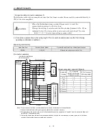
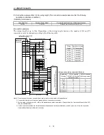
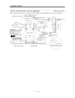
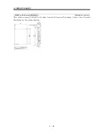
SH13 outline drawing Reference
(Dimension unit: mm)
This outline drawing is based on the data from Sony Precision Technology. Contact Sony Precision
Technology for this outline drawing.
SONY
SH13-
124
1240
2
450
434
620
114
1140
2
420
394
570
102
1020
2
380
354
510
092
920
1
507
460
082
820
1
457
410
077
770
1
432
385
072
720
1
407
360
067
670
1
382
335
062
620
1
357
310
057
570
1
332
285
052
520
1
307
260
047
470
235
042
420
210
037
370
185
032
320
160
027
270
135
022
220
110
017
170
85
012
120
60
007
70
35
L
n
A
P1
Z
mm
mm
mm
mm
Scale full length = L + 105
Scale mounting hole pitch = L + 94
Middle support mounting
position = A
Middle support mounting
position = A
(n - 1) P1
Middle support A
Middle support B
Home position mark
Head cable length = 1000
(20)
12
Scanning unit
2
12 56
80
40
Z
4
8
4.
6
26.5
1
3
Home position
Effective measurement length = L
Left side measurement end
Right side measurement end
M4 (depth 10)
3
3
3
74
M4 (depth 10)
12
36
4.
5
20
2 - 5, 8.2 spot facing
depth 5
Air intake (M5)
(5.5)
Depth 5
Middle support B mounting side face
Middle support A mounting side face
21
10.5
10
5
22
5
5
6
6
19
15
26
43
.5
7.5
13
2.5
0.3
Effective measurement length
Middle support
Middle support mounting
hole pitch
Home position
5.5
35
26
(25)
43.5
5
19
5.
8
Summary of Contents for Melservo-J2-SUPER series
Page 19: ...1 6 1 FUNCTIONS AND CONFIGURATION MEMO...
Page 49: ...2 30 2 LINEAR SCALES MEMO...
Page 85: ...5 8 5 PARAMETERS MEMO...

