


10.2 Troubleshooting in Bus Connection
10 - 13
9
M
A
IN
TE
N
A
N
C
E AN
D
IN
SP
ECTIO
N
10
TROU
BLES
H
OOTING
APP
ENDICES
10.2.2 Further locating error positions
If the function of the PLC cannot be recovered even when the module on which an error occurs is replaced with a new
one, the error may be caused by the effect from another module.
Disconnect the extension cables and bus connection cables in order from the modules starting from the module located
furthest from the operating position in the system, and check for the status of occurrence of the error each time the
cables are disconnected until the error does not occur.
The module or extension cables/bus-connection cables disconnected immediately before the error does not occur are
considered to cause the error.
Examples of the ways of further locating error positions are shown below. (When use the extension base unit QnASCPU)
Repeat the examples 1 and 2 above to locate error positions.
POINT
POINT
POINT
Notes on narrowing the error part range
The checks stated above are effective to locate a noise invading route when the mis-operation is caused by noise.
1. When disconnecting the extension base units in order, use only an ENDinstruction for the sequence
program, and any error resulting from the sequence program will not occur, and the status of
occurrence of errors will be obtained easily.
2. When the frequency of occurrence of an error is low, check the error by taking a rather long time with
the modules disconnected.
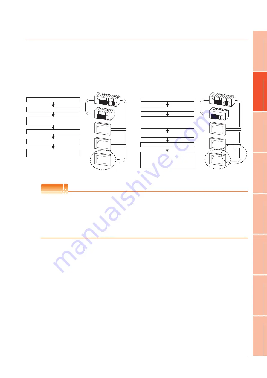
Turn off the power of the GOT.
Disconnect the bus-connection cable
(IN side) from the final stage GOT.
If an error does not occur, the final
stage GOT may be faulty.
Example 1:
Example 2:
Turn off the power of the PLC.
Turn on the power of the PLC.
Turn on the power of the GOT.
Turn off the power of the GOT.
Disconnect the bus-connection cable
(OUT side) from the GOT located one
stage before the final stage.
If an error does not occur, the final
stage GOT and the bus-connection
cable before the final stage may be
faulty.
Turn off the power of the PLC.
Turn on the power of the PLC.
Turn on the power of the GOT.
Summary of Contents for GOT 1000 GT16
Page 1: ...GT16 User s Manual Hardware ...
Page 2: ......
Page 14: ...A 12 INDEX REVISIONS WARRANTY ...
Page 210: ...App 17 ...
Page 212: ...Index 2 Transportation Precautions App 15 U USB environmental protection cover 2 17 8 19 ...
Page 217: ......