


6.3 Mounting Position
6 - 9
1
OV
E
R
VI
EW
2
SYSTE
M
CO
N
F
IG
UR
A
T
IO
N
3
S
P
E
CI
F
ICA
T
ION
S
4
P
A
R
T
NA
ME
AND
SETTING
S
5
EMC AND
LO
W
VO
LT
AG
E
DIRE
C
T
IVE
6
IN
ST
ALLA
TIO
N
7
WIRING
8
OP
TI
ON
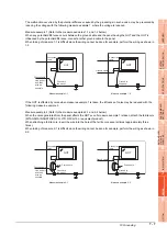
(e) For GT1655
The control panel side installation unit cannot be installed within 25mm (0.98inch) from the GOT.
When the CF card interface built in the GOT (A drive) is used, the unit cannot be installed within the range
of 100mm (3.94inch) (horizontal) 68mm (2.68inch) (vertical) from the right side of the hole for installing
GOT, viewed from the rear side.
The CF card cannot be installed or removed.
When the other extension units are used, the control panel side installation unit cannot be installed in the
areas shown in the following figure.
Hole for
installing GOT
(View from
the rear side)
Prohibited area for installation
with an extension unit
Prohibited area
for installation
with CF card
interface (A drive)
X
130
(5.12)
100
(3.94)
15
(0.59)
68
(2.68)
Extension unit
Model
X (Unit: mm(inch))
Bus connection unit
GT15-ABUS, GT15-ABUS2,
GT15-75ABUS2L, GT15-75ABUSL
58(2.28)
GT15-QBUS, GT15-QBUS2,
GT15-75QBUSL, GT15-75QBUS2L
79(3.11)
Serial communication unit
GT15-RS2-9P, GT15-RS4-9S
GT15-RS4-TE
57(2.24)
MELSECNET/H communication unit
GT15-J71LP23-25
116(4.57)
GT15-J71BR13
72(2.83)
CC-Link IE Controller Network
communication unit
GT15-J71GP23-SX
64(2.52)
CC-Link IE Field Network
communication unit
GT15-J71GF13-T2
50(1.97)
CC-Link communication unit
GT15-J61BT13
31(1.22)
Printer unit
GT15-PRN
36(1.42)
CF card extension unit
GT15-CFEX-C08SET
104(4.09)
External I/O unit
GT15-DIO, GT15-DIOR
65(2.56)
*
1
Prohibited areas for installing the control panel side installation unit with the extension unit
do not exist.
Summary of Contents for GOT 1000 GT16
Page 1: ...GT16 User s Manual Hardware ...
Page 2: ......
Page 14: ...A 12 INDEX REVISIONS WARRANTY ...
Page 210: ...App 17 ...
Page 212: ...Index 2 Transportation Precautions App 15 U USB environmental protection cover 2 17 8 19 ...
Page 217: ......