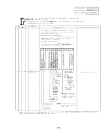
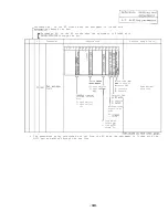


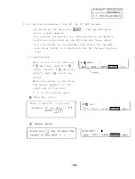


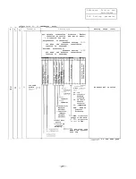

(3) Parameters to be controlled on spindle amplifier side
By pressing the
key,
the spindle parameter screen
8.
appears.
These parameters are sent from the NC when the spindle
amplifier is linked with the bus line.
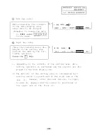
(Note 1) Although the same parameters can be set from the
spindle amplifier,
when the bus line is linked,
those being set from the NC become valid.
(Note 2) When the SF-CA card dip switch (see Section
and Appendix
is turned on
mark),
the parameters being set from the NC
are invalidated and those set from the spindle
amplifier is validated.
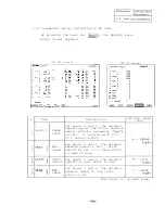
CRT
screen]
[SPINDLE
4coO
4
4
0 m
5
0 21
6
2
22
7
3
23
4
0 24
2
57
56
3
0 27
43
4
3
61
0 30
62 63
6601
6
4
0 32
0
64
I
I
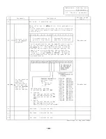
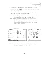
C R T
s c r e e n ]
SPEC.
1
1
133 13
25GRAl
1
2 PG2
20 14
2
1
3 PGC 10.00 15
3
1
4
1.00 16
0023 4
1
5
220
17
1
6 CSP
20 18
50 30
2
7 PST
2048 19 CSN
300 31 3
8
0 20 SDT
1032 4
9
21 TLM
10 33
10
22
63 34
11
23
60 35
12
24 TYP
1 36
BASE
AXIS
SERVO
MENU
(Note
3) After these parameters are set, the power of
the NC should be turned off.
After it is turned
on,
the parameters are validated.
Summary of Contents for FREQROL-SF
Page 100: ... 3 Display lamps See Appendix 8 2 4 Check terminals See Appendix g 3 95 ...
Page 101: ......
Page 102: ......
Page 103: ......
Page 104: ......
Page 105: ......
Page 106: ......
Page 107: ......
Page 108: ......
Page 109: ......
Page 110: ......
Page 111: ......
Page 128: ......
Page 129: ......
Page 130: ......
Page 131: ......
Page 132: ......
Page 133: ......
Page 134: ......
Page 135: ......
Page 136: ......
Page 137: ......
Page 138: ......
Page 139: ......
Page 140: ......
Page 141: ......
Page 142: ......
Page 143: ......
Page 144: ......
Page 145: ......
Page 146: ......
Page 147: ......
Page 148: ......
Page 149: ......


